Skip to content
Andwin Circuits
  • Home
  • ProductsExpand
    • HDI multilayer PCB
    • Rigid Flex PCB
    • Flex pcb
    • Special PCBExpand
      • High Frequency PCBExpand
        • Rogers RO4350B PCB
        • Rogers RO4003 pcb
        • Rogers RO3003 PCB
        • Rogers 5880 PCB
        • DICLAD 527 PCB
        • Taconic TLX series
        • Taconic TLX-8 RF PCB
        • Taconic TLX-9 RF PCB
      • High speed pcbExpand
        • Megtron 6 High Speed PCB
        • TU-872 SLK Sp High Speed
      • High TG PCBExpand
        • SHENGYI SH260 PCB
        • ISOLA 370HR PCB
        • ISOLA IS410 PCB
        • ISOLA IS420 PCB
      • Heavy copper PCB
      • Copper coin pcb
      • Copper inlay PCB
    • Metal Core PCBExpand
      • Copper core pcb
      • Aluminum PCB
      • 2 Layers Aluminum PCB
      • Direct thermal MCPCB
      • 2 Layers Direct Thermal
    • Ceramic PCBExpand
      • DPC ceramic PCB
      • DBC ceramic PCB
      • Thick film Ceramic PCB
      • Al2O3 Alumina PCB
      • AIN ALN ceramic PCB
      • IGBT Ceramic PCB
  • ServiceExpand
    • PCB Assembly
    • Quick turn PCB assembly
    • PCBA conformal coating
  • IndustryExpand
    • Telecommunication
    • IoT and Wireless
    • Industrial Control
    • Thermal management
    • Power and Energy
    • IC test board
    • Automative
    • Medical
  • CapabilityExpand
    • Rigid PCB
    • Rigid flex PCB
    • Metal core PCB
    • PCB Assembly
  • TechnologyExpand
    • Blogs
    • Via in pad
    • PCB E-test
    • PCB stack up
    • MCPCB panelization
    • Controlled impedance PCB
  • AboutExpand
    • About us
    • Certification
    • Factory Tour
  • Contact
Andwin Circuits
Home / About PCB heating circuit design

About PCB heating circuit design

ByGrace July 7, 2025July 7, 2025

Since the product needs to work in a low temperature environment, it has exceeded the minimum operating temperature requirements of some components on the circuit board, so it is necessary to add an additional heating circuit so that the overall temperature of the PCB board can be kept within the range required by the components.

1.Basic idea

    The main purpose of the heating circuit is to heat and insulate the PCB board at low temperatures, so that its temperature can be kept above the minimum operating temperature of the device, so there is no need to accurately control the temperature. Therefore, the following plan is formulated to use resistors and NTC thermistors to divide the voltage and control a MOS tube or triode. When the temperature is low to a certain threshold, the resistor and NTC resistor divider voltage increases, and the heating circuit is turned on. When the temperature rises, the divider voltage drops and the circuit is closed.

    2.Implementation of each part of the circuit

      The triode and MOS tube choose the commonly used SOT-23 package. Comparing the commonly used triodes and MOS tubes, under the same package, the on-current supported by the MOS tube is generally much larger than that of the triode, so we choose the MOS tube. Through comparison, we finally choose the LRC model LN2302BLT1G, and the NTC resistor chooses the commonly used NCP15WF104F03RC. According to the power of the heating circuit, we choose to use a 10 ohm resistor in a 1210 package as a heating device, and the total power is controlled to 2.5W.

      The final schematic design is as follows:

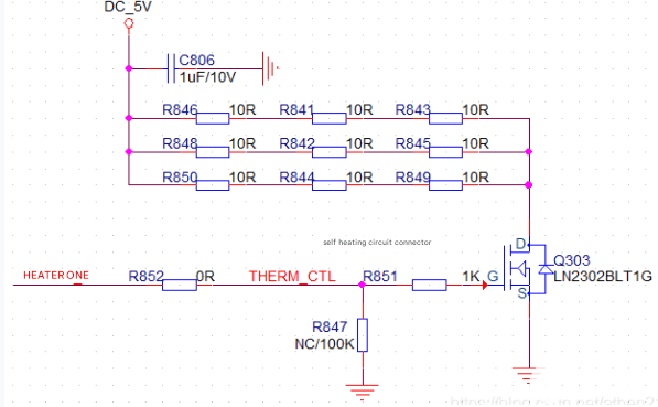
      Heating circuit part

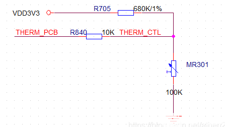
      NTC temperature control part

      Description of the schematic diagram, in the schematic diagram, the signal THERM_PCB is used as an analog signal to the ADC port of the microcontroller on the PCB board, which can be used as the temperature measurement of the PCB board. HERTER_EN is connected to the control IO of the microcontroller, and the IO is set to high resistance. When the heating circuit is out of control, the IO is pulled high, and the MOS tube is forced to be closed as a safety measure.

      Determination of the values ​​of the control circuit:

      In the above circuit, the main parameter to be determined is the value of R705, which directly determines when the MOS tube Q302 is turned on by the voltage divider resistor R705. First, determine that this circuit uses 5 degrees above zero as the dividing point for turning on and off the heating circuit.

      First, we check the resistance value at 5 degrees above zero from the specifications of the NTC resistor. As shown in the figure below, its resistance value is 272K ohms at the corresponding temperature.

      Contact us for PCB quote now |

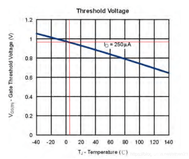
      Next, confirm the corresponding MOS tube turn-on voltage at 5 degrees above zero. From the chart provided in the specification book, it can be found that the turn-on voltage of the MOS at 5 degrees is 0.97V.

      Finally, calculate the voltage divider resistor based on the above values ​​and select the value of 680K.

      3.Design of heating circuit board

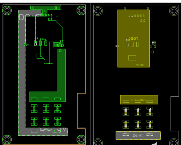
        Since the heating circuit is placed on a small PCB board and then set up between two main PCB boards. Therefore, the layout of the heating components is designed according to the needs of the two main PCB boards.

        The areas that need to be heated on the two main PCBs are located in the same direction, so on the heating circuit board, the heating resistors are concentrated in the corresponding areas so that the heat reaches the required places first. The extra copper on the board is removed, and the NTC resistor is placed on one of the two main PCB boards. Add a thermal conductive silicone pad between the heating area of ​​the board and the two main PCB boards to enhance heat conduction.

        Contact us for PCB quote now |

        4.Physical board test and conclusion

          Using the physical board for testing, the maximum temperature rise of these circuits can reach 20 degrees when the jumper is used for full-rate heating at room temperature. Tested in a low temperature box, the heating circuit is controlled, and the circuit will start to turn on at around 7 degrees, and it will reach the designed full power when it reaches -4 degrees.

          Advantages and disadvantages of this electric control circuit:

          Advantages: The heating control circuit schematic is simple, the parameters are easy to determine, and the final test results meet the expected design goals.

          Disadvantages: The heating speed is slow, it takes a long time to reach temperature equilibrium, and there will be temperature fluctuations during the heating process. It cannot be used in situations such as precise heating.

          Contact us for PCB quote now |
          Post Tags: #aluminum clad pcb#aluminum core pcb#aluminum pcb#pcb design#pcb heating

          Post navigation

          Previous Previous
          PCB signal line layout
          NextContinue
          Guidelines for Drawing PCB Schematic

          Search

          Search

          Products

          • HDI Multilayer PCB
          • Rigid Flex PCB
          • Flex pcb
          • High Frequency PCB
          • High speed pcb
          • Heavy copper PCB
          • Metal Core PCB
          • Ceramic PCB

          Address

          Andwin Circuits Co.,Limited
          Email: sales@andwinpcb.com
          Tel: +86 755 2832 9394
          Fax:+86 755 2992  6717
          ADD:1-2F-1217,HouDeQun Industrial park,
          NanTing RD NO.56,ShaJing,BaoAn,Shenzhen 518104,GuangDong,China

          Products

          • HDI Multilayer PCB
          • Rigid Flex PCB
          • Flex pcb
          • High Frequency PCB
          • High speed pcb
          • Heavy copper PCB
          • Metal Core PCB
          • Ceramic PCB

          Technology

          • Blogs
          • Via in pad
          • PCB E-test
          • PCB stack up
          • Metal core PCB panelization
          • Controlled impedance PCB

          CERTIFICATION

          Certification >>


          Copyright© 2003 - 2026 Andwin | All Rights Reserved | Powered by Andwin

          Scroll to top
          • Home
          • Products
            • HDI multilayer PCB
            • Rigid Flex PCB
            • Flex pcb
            • Special PCB
              • High Frequency PCB
                • Rogers RO4350B PCB
                • Rogers RO4003 pcb
                • Rogers RO3003 PCB
                • Rogers 5880 PCB
                • DICLAD 527 PCB
                • Taconic TLX series
                • Taconic TLX-8 RF PCB
                • Taconic TLX-9 RF PCB
              • High speed pcb
                • Megtron 6 High Speed PCB
                • TU-872 SLK Sp High Speed
              • High TG PCB
                • SHENGYI SH260 PCB
                • ISOLA 370HR PCB
                • ISOLA IS410 PCB
                • ISOLA IS420 PCB
              • Heavy copper PCB
              • Copper coin pcb
              • Copper inlay PCB
            • Metal Core PCB
              • Copper core pcb
              • Aluminum PCB
              • 2 Layers Aluminum PCB
              • Direct thermal MCPCB
              • 2 Layers Direct Thermal
            • Ceramic PCB
              • DPC ceramic PCB
              • DBC ceramic PCB
              • Thick film Ceramic PCB
              • Al2O3 Alumina PCB
              • AIN ALN ceramic PCB
              • IGBT Ceramic PCB
          • Service
            • PCB Assembly
            • Quick turn PCB assembly
            • PCBA conformal coating
          • Industry
            • Telecommunication
            • IoT and Wireless
            • Industrial Control
            • Thermal management
            • Power and Energy
            • IC test board
            • Automative
            • Medical
          • Capability
            • Rigid PCB
            • Rigid flex PCB
            • Metal core PCB
            • PCB Assembly
          • Technology
            • Blogs
            • Via in pad
            • PCB E-test
            • PCB stack up
            • MCPCB panelization
            • Controlled impedance PCB
          • About
            • About us
            • Certification
            • Factory Tour
          • Contact
          Search