FPC vs. PCB: Understanding Flexible Printed Circuits and Their Differences from Traditional PCBs
Introduction to FPC and PCB
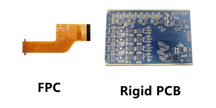
In the world of electronics manufacturing, two critical components form the backbone of most devices: Printed Circuit Boards (PCBs) and Flexible Printed Circuits (FPCs). While both serve as platforms for mounting and connecting electronic components, they differ significantly in their materials, construction, and applications.
PCBs, the more traditional option, are rigid boards that have been used in electronics for decades. They provide a stable foundation for components and are known for their durability and ease of manufacturing. FPCs, on the other hand, represent a more modern solution, offering flexibility that enables innovative product designs and applications where rigid boards would be impractical.
This article will explore what FPC material is, examine its composition and properties, and provide a detailed comparison between FPCs and PCBs across various parameters including structure, manufacturing processes, applications, and cost considerations.
What is FPC Material?
Definition and Composition of FPC
Flexible Printed Circuits (FPCs) are made from thin, flexible insulating polymer films with conductive circuit patterns. The base material is typically polyimide (PI), though other polymers like polyester (PET) or polyethylene naphthalate (PEN) are sometimes used. Polyimide is preferred for its excellent thermal stability, chemical resistance, and mechanical properties.
The conductive elements in FPCs are usually made of rolled annealed copper foil, which is more flexible than the electrodeposited copper used in rigid PCBs. The copper is often coated with a thin protective layer, typically gold or tin, to prevent oxidation and improve solderability. Adhesives bond these layers together, although newer adhesive-less constructions are becoming popular for high-performance applications.
Key Properties of FPC Materials
FPC materials exhibit several unique properties that make them indispensable in modern electronics:
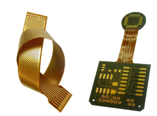
- Flexibility and Bendability: The primary characteristic of FPC materials is their ability to bend and flex repeatedly without damaging the conductive traces. This allows for dynamic flexing applications or compact packaging in static installations.
- Thin and Lightweight: FPCs are significantly thinner and lighter than rigid PCBs, making them ideal for space-constrained or weight-sensitive applications like mobile devices and wearable technology.
- Thermal Stability: High-quality polyimide films can withstand temperatures up to 400°C, enabling FPCs to endure soldering processes and high-temperature operating environments.
- Chemical Resistance: The materials resist most solvents, acids, and oils, ensuring reliability in harsh environments.
- Dielectric Properties: FPC materials maintain stable dielectric properties across a wide frequency range, making them suitable for high-speed digital and RF applications.
Types of FPC Materials
Several material combinations are used in FPC manufacturing:
- Single-sided FPC: The simplest construction with conductive traces on one side of the flexible film.
- Double-sided FPC: Features conductive layers on both sides with plated through-holes for interconnections.
- Multilayer FPC: Combines multiple conductive layers with insulating layers between them for complex circuits.
- Rigid-Flex: Hybrid constructions that integrate rigid PCB sections with flexible interconnections in a single unit.
Fundamental Differences Between FPC and PCB
Structural Differences
The most apparent difference between FPCs and PCBs lies in their physical structure. PCBs are rigid, typically made from fiberglass-reinforced epoxy laminate (FR-4), while FPCs are flexible, using polyimide or similar flexible polymers as their base material.
PCB construction involves multiple layers of copper traces sandwiched between rigid insulating layers. The thickness typically ranges from 0.4mm to 3.2mm, providing substantial mechanical support. In contrast, FPCs are much thinner, usually between 0.1mm to 0.3mm, with the flexibility coming from the polyimide base and thin copper layers.
The copper used in FPCs is typically rolled annealed copper, which has better flexibility than the electrodeposited copper used in PCBs. This allows the FPC to withstand repeated bending without cracking the conductive traces.
Manufacturing Process Variations
While both FPCs and PCBs share some manufacturing steps like etching and plating, their production processes differ significantly:
PCB Manufacturing:
- Cutting rigid laminate material to size
- Drilling holes for through-hole components and vias
- Electroplating to create conductive through-holes
- Applying photoresist and patterning the circuit
- Etching away unwanted copper
- Applying solder mask and silkscreen
- Surface finishing (HASL, ENIG, etc.)
FPC Manufacturing:
- Coverlay application (instead of solder mask)
- Precision patterning of thinner materials
- Specialized handling to prevent damage to flexible layers
- Different lamination processes using heat and pressure
- Often requires specialized equipment for handling flexible materials
FPC manufacturing typically requires cleaner environments and more precise control as the thin materials are more susceptible to defects like wrinkles or tears during processing.
Performance Characteristics
The performance differences between FPCs and PCBs stem from their material properties:
- Current Carrying Capacity: PCBs generally handle higher currents due to thicker copper layers and better heat dissipation.
- Signal Integrity: FPCs can offer better high-frequency performance due to more consistent dielectric properties.
- Thermal Management: PCBs dissipate heat better, while FPCs may require special design considerations for thermal issues.
- Environmental Resistance: FPCs often perform better in high-vibration environments due to their ability to flex.
- Reliability: PCBs are generally more reliable for static applications, while FPCs excel in dynamic flexing scenarios.
Applications: Where FPCs Excel vs. PCBs
Typical PCB Applications
Rigid PCBs are the backbone of most electronic devices and are found in:
- Computer motherboards and expansion cards
- Television and monitor control boards
- Power supplies and power conversion equipment
- Automotive control units (except for flexible connections)
- Industrial control systems
- LED lighting systems
- Consumer appliances
These applications benefit from the PCB’s rigidity, durability, and ability to support heavier components and heat-generating elements.
Typical FPC Applications
FPCs find use in applications where flexibility, space savings, or weight reduction are critical:
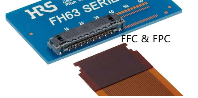
- Smartphones and tablets (display connections, camera modules)
- Wearable devices (smartwatches, fitness trackers)
- Medical devices (hearing aids, imaging equipment)
- Automotive electronics (dashboard displays, sensor connections)
- Aerospace and military equipment (where weight and space are critical)
- Consumer electronics (foldable devices, compact cameras)
- Industrial equipment (moving sensor connections)
In these applications, FPCs enable innovative form factors and reliable performance in dynamic environments where rigid boards would fail.
Hybrid Applications: Rigid-Flex PCBs
Some applications benefit from combining both technologies in rigid-flex designs:
- Medical imaging equipment
- High-reliability military/aerospace systems
- Advanced automotive electronics
- Foldable smartphones and tablets
- Complex industrial equipment
These hybrid solutions offer the best of both worlds: the stability of rigid sections for component mounting and the flexibility of FPCs for interconnections and compact packaging.
Cost Considerations and Design Factors
Material Costs Comparison
Generally, FPC materials are more expensive than PCB materials on a per-area basis:
- Standard FR-4 PCB material: $1-$5 per square foot
- Polyimide FPC material: $5-$20 per square foot
- High-performance FPC materials: up to $50 per square foot
However, the total system cost may favor FPCs when considering:
- Reduced assembly costs (fewer connectors needed)
- Space savings enabling smaller enclosures
- Weight reduction benefits (in aerospace/mobile applications)
- Reliability improvements reducing warranty costs
Design Considerations
Designing with FPCs requires special considerations:
- Bend Radius: Must maintain minimum bend radius to prevent damage
- Dynamic vs. Static Flexing: Different design rules apply
- Component Placement: Avoid placing components in bend areas
- Strain Relief: Proper strain relief must be designed at connection points
- Thermal Management: May require special heat dissipation techniques
PCB designs have their own set of rules, but generally allow more flexibility in component placement and thermal management.
Manufacturing Yield and Complexity
FPC manufacturing typically has lower yields than PCB manufacturing due to:
- Handling challenges with thin, flexible materials
- Higher sensitivity to environmental conditions
- More complex lamination processes
- Greater susceptibility to dimensional changes
This contributes to the higher cost of FPCs and makes prototyping more expensive compared to PCBs.
Future Trends in FPC and PCB Technology
Advancements in FPC Materials
Ongoing research is developing new FPC materials with:
- Higher temperature resistance
- Improved flexibility and bend endurance
- Better adhesion between layers
- Enhanced thermal conductivity
- Stretchable circuit capabilities
These advancements will expand FPC applications into more demanding environments and enable new product designs.
PCB Technology Developments
PCB technology continues to evolve with:
- Higher density interconnects
- Embedded components
- Improved high-frequency materials
- More environmentally friendly manufacturing processes
- Additive manufacturing approaches
These developments help maintain PCBs as the preferred solution for many standard applications.
Convergence of Technologies
The line between FPCs and PCBs continues to blur with:
- Thinner, more flexible PCB materials
- Improved rigid-flex technologies
- 3D printed electronics combining flexible and rigid sections
- Hybrid approaches for next-generation electronics
This convergence is enabling innovative product designs that leverage the strengths of both technologies.
Conclusion
FPCs and PCBs serve distinct but complementary roles in modern electronics. FPC materials, primarily based on polyimide films with rolled copper conductors, offer unmatched flexibility and space savings for applications where rigid boards are impractical. Traditional PCBs provide robust, cost-effective solutions for most standard electronic assemblies.
The choice between FPC and PCB depends on the specific application requirements, including flexibility needs, space constraints, environmental conditions, and budget considerations. As electronics continue to evolve toward smaller, more flexible form factors, FPC technology is growing in importance, while PCB technology advances to maintain its dominance in conventional applications.
Understanding the material properties, manufacturing processes, and performance characteristics of both FPCs and PCBs enables designers to select the optimal solution for their specific needs, often combining both technologies in innovative ways to create the next generation of electronic devices.