Why are resistors used in PCBs?
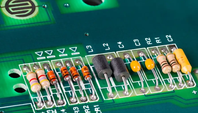
Resistors are one of the most basic components used in printed circuit boards (PCBs). They are passive devices that block the flow of current in a circuit. PCB resistors can control, divide, stabilize, connect circuits, and more. They come in a variety of resistance values, sizes, power ratings, and tolerances to meet different circuit requirements.
Resistance value (measured in ohms) represents the resistance to the flow of current. Resistors obey Ohm’s law, which states:
V = Ir
Where V is voltage in volts, I is current in amperes, and R is resistance in ohms
So for a given voltage, a higher resistance results in a smaller current. Resistors convert electrical energy into heat and must dissipate it. They are purely passive devices and cannot amplify or increase power.
Why are resistors used in PCBs?
Here are some of the main applications of resistors in PCB circuits:
Current Limiting – Resistors prevent damage by limiting the current to delicate LEDs, integrated circuits, and other components.
Voltage division – Series resistors form a voltage divider to get a lower voltage from a power supply.
Pull-up/pull-down – Used with digital logic circuits to ensure a known logic voltage level when the input is not driven.
Biasing – Provides proper DC bias voltage or current to transistor amplifiers and other analog circuits.
Feedback – Essential for op amps, ADCs, DACs, and other analog circuits to control gain and response.
Pulse shaping – Combined with capacitors to form RC timing circuits for pulse generation.
ESD protection – Prevents damage from electrostatic discharge.
Heaters – Wirewound power resistors convert electrical energy into heat.
In short, resistors regulate, stabilize, and protect electronic circuits. Without them, modern PCBs would not function properly.
Types of PCB Resistors
There are a variety of resistor types available to suit different applications. They can be categorized based on construction, material composition, size, and other factors.
Here are some of the most common PCB resistor types:
Carbon composition resistors
Carbon composition resistors are the oldest type of resistors. They are made of a solid cylindrical rod of ceramic and carbon particles. Key features of carbon composition resistors:
Low cost, but poor tolerance due to temperature effects (±10%)
Used where accuracy is not critical
Available in 1/4 to 2 Watt power ratings
Commercial grade stability
Noisier than other types
Susceptible to voltage coefficient issues
Carbon film resistors
Carbon film resistors have a thin film of carbon deposit on a ceramic rod. They exhibit better performance than carbon compositions:
Improved tolerance (±5%) and stability
Low temperature resistivity
Available in 1/8 to 1 Watt power ratings
Extremely low inductance and capacitance
Low noise operation
Better withstanding voltage surges
Metal film resistors
For better accuracy and stability, metal film resistors are used. They are made by depositing a thin film of nickel chromium or tin oxide on a ceramic substrate. Key features of metal film resistors:
Better tolerance (±1%) and temperature stability
Lower noise than carbon composition and carbon film
Power ratings range from 1/10 watt to 1 watt
Ability to handle higher peak voltages
Low voltage coefficient and good stability
Metal oxide film resistors
Instead of using a metal film, metal oxide film resistors use a metal oxide material such as tin oxide. This provides further improvements:
Excellent tolerance down to ±0.5%
Extremely stable over time and temperature
Low thermal EMF, reduced noise
High frequency capability up to the GHz range
High reliability and pulse handling capability
Applied in high precision test equipment
Wirewound resistors
Wirewound resistors achieve their resistance by winding a resistive wire around a ceramic core. Key features include:
High power handling capability, up to 100 watts or more
Available for shallow resistance values
Inductive, not suitable for high frequency use
Commercial tolerances are around ±5%
Usually packaged in aluminum or ceramic housings
Prone to thermal EMF effects under shock/vibration
Foil resistors
For shallow resistance values below 1 ohm, foil resistors are used. They consist of a thin foil of a metal alloy bonded to a ceramic substrate.
Features include:
Resistance values down to milliohms
High accuracy with ±0.005% tolerances available
Low TCR with excellent stability
High current carrying capacity
All welded construction, no helix
Common in aerospace applications
Ceramic resistors
Ceramic composition resistors are made of a layer of ruthenium oxide glaze fused to a ceramic body. They offer exceptional performance:
Extremely tight tolerances down to ±0.02%
Ultra-low temperature coefficient
High stability over time and environmental stress
Withstands repeated thermal shocks without drift
Used in high reliability aerospace and military applications
Fusible Resistors
Fusible power resistors contain a built-in fusible link that blows when excessive current is drawn. Under normal conditions, they behave like any other fixed resistor. Key features of fusible resistors include:
Provides overload protection for circuits
Power ratings from 1 to 5 watts
Fuse opens safely before the main resistor body overheats
Can be manually reset by replacing the fuse
Commonly used in power supply, distribution circuits
Trimming Resistors
Trimming resistors have adjustable resistance values obtained by mechanical means (screws or sliding contacts). This allows the resistance to be “fine tuned” during circuit calibration and testing.
Characteristics of Trimmer Resistors:
Variable within a limited range, typically 20-30%
Set to precise value using screwdriver or small adjustment tool
Sealed construction prevents environmental contamination
Through hole and SMD packages available
Widely used for analog or precision circuit fine tuning
Thermistors
Thermistors are resistors using semiconductor materials with significant temperature coefficients of resistance. This means that their resistance values vary greatly with temperature.
Characteristics of Thermistors:
Used for temperature measurement, compensation and control
NTC types decrease in resistance as temperature increases
PTC types increase in resistance as temperature increases
Response times vary from seconds to minutes
The relationship between resistance and temperature is highly nonlinear
Varistor
Varistor is a voltage dependent resistor made of specially formulated metal oxide materials.
Their basic function is transient voltage suppression:
Resistance drops dramatically with applied voltage
Absorbs and limits transient voltage spikes during ESD or surges
Used to protect sensitive electronic equipment from damage
Bidirectional operation for AC or DC circuits
Energy handling capability specified by joule ratings
Response time (nanoseconds)
Photoresistors
Photoresistors, also known as light-dependent resistors ( LDRs ), have resistance that decreases when exposed to light. They are made from semiconductor materials such as cadmium selenide or cadmium sulfide. Key Features:
Resistance can vary by several orders of magnitude between dark and light conditions
Excellent sensitivity to visible and infrared wavelengths
Used in electronics that use light for sensing and activation
Slow response time makes them unsuitable for fast light signals
Packaging must allow light to reach the photosensitive area
Magnetoresistors
Magnetoresistors are resistors made from materials whose resistance changes with a magnetic field. Some types include:
Permalloy magnetoresistors using nickel-iron thin films
GaAs semiconductors
Giant magnetoresistors multilayer devices
Tunnel magnetoresistors utilizing magnetic tunnel junctions
Useful properties of magnetoresistors include:
Detects magnetic field strength and direction
Provides electrical isolation from the sensing medium
Rugged and operates over a wide temperature range
Used in magnetic field sensors, current sensors, isolators
Exhibits high sensitivity to small magnetic changes
Chip resistors
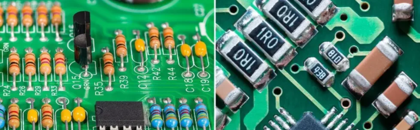
Surface mount device (SMD) resistors are designed for surface mount PCB assemblies rather than through-hole mounting. They are much smaller and allow very high component density on the board.
Some features of chip resistors:
Rectangular, square, or oval ceramic body with terminals on the bottom
Terminals are thick film, solder coated nickel strips
Marked with numeric resistance codes instead of color bands
Resistance ranges typically from 10 ohm to 22 Mohm
Power ratings from 0.05 watt to 1 watt
Tolerances as low as ±0.1%
Sizes specified in imperial (01005) or metric (0402) codes
The tiny size of SMD resistors enables more components to be fitted into increasingly smaller PCBs. Automated assembly and cost savings over through-hole resistors are additional advantages.
Resistor Marking Codes
Finding Resistors by Color Code
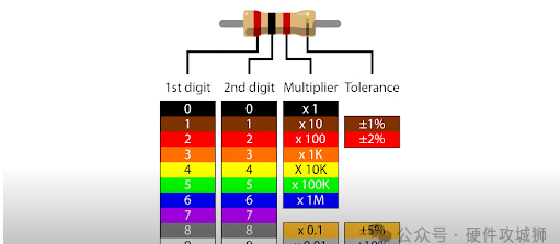
Because resistors are so small, they must use color bands, alphanumeric codes, or other markings printed directly on the resistor body to indicate their resistance value and tolerance.
Color bands
The color ring system has been used to indicate resistor values since the 1920s.
Three-ring resistors have two important numerical resistance color bands and a third multiplier ring
Four-ring resistors add a fourth tolerance color band for greater precision
Five-ring and six-ring resistors also exist for high stability requirements
SMD Marking Codes
Due to their smaller size, SMD resistors use compact numeric resistance and multiplier codes instead of color bands.
Some typical schemes are:
Three-digit code – first two digits for resistance, third digit for multiplier
Four-digit code – first three digits for resistance, fourth digit for multiplier
EIA-96 system – 2 digits for resistance, letter for multiplier
So 472 equals 47 x 100 = 4.7KΩ. 15R2 = 15 x 0.01 = 150 ohms.
Laser trimming of the resistor layer is also used to achieve very tight tolerance SMD resistor values.
How to Choose the Right Resistor
Choosing the right resistor for a particular PCB application involves several important considerations:
Resistor Value
The optimal resistor depends on the circuit design requirements and is calculated using Ohm’s Law. The standard EIA decade value is usually chosen.
Tolerance
The tolerance indicates the accuracy of the resistor’s nominal value. Tighter tolerances of ±1% or better are used for precision circuits. Larger tolerances of about ±5% or ±10% are acceptable for non-critical applications to reduce cost.
Power Rating
The power rating must exceed the maximum expected power dissipation of the resistor. The power rating is determined by the physical size. 1/4 Watt (or 250mW) can handle most low-power circuits. Power supplies or heaters may require higher wattages.
Temperature Coefficient
The inherent change in resistance per degree of temperature change. A lower coefficient provides better stability in precision circuits. The maximum operating temperature must also be considered.
Voltage Rating
The maximum voltage drop across the resistor must be exceeded with a safety margin. Power supplies and other high-voltage applications require higher voltage ratings.
Size
Physical size can determine SMD vs. through-hole form. Height restrictions may apply to densely packed boards. High-power resistors are larger than low-power resistors.
Noise
High-gain analog circuits and RF/data transmission lines should use low-noise film resistors. Wirewound coils have some inductance, which can generate noise.
Response Time
Select resistors with appropriate transient response for timing circuits, pulsed operation, and high-frequency applications.
Considering these factors, the best PCB resistor type and specifications can be selected.
PCB Resistor Applications
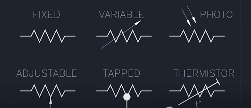
Resistor Symbol
Resistors are ubiquitous in a variety of printed circuit board applications, including:
Voltage Divider
Two or more resistors connected in series across a voltage source form a simple but useful voltage divider circuit. This generates a lower voltage tap from a higher supply voltage.
Voltage dividers are used in power supplies, bias networks for transistor amplifiers, ADC interfaces, and many other places where a fraction of a voltage rail is needed. Careful selection of the appropriate resistor values results in the desired voltage division ratio.
Current Limiting
Putting resistors in series with LEDs, integrated circuits, and other precision electronic components limits the current that flows through them. The resistor value is calculated to reduce excess voltage beyond what is required by the device. It prevents damage from inrush current, overloads, or short circuits.
Pull-up/Pull-down
Pull-up and pull-down resistors are connected between the integrated circuit logic output and the positive or negative power rail (ground). It ensures a known logic voltage level when the IC output is high.
Pull-up/pull-down resistors provide defined default conditions that prevent logic errors and false triggering. They are essential for reliable operation of all digital logic families.
Bias Networks
Providing the proper DC bias voltage or current level through resistors allows analog integrated circuits such as transistor amplifiers and operational amplifiers to operate in their linear region. Bias resistors help stabilize these active devices in optimal quiescent conditions to meet circuit design requirements.
Feedback Circuits
Resistors are integral components in the feedback loops of op amps, ADCs, DACs, and other analog circuits. They control gain, frequency response, stability, and output impedance depending on the intended function.
Timing Circuits
Combining resistors with capacitors to form RC timing circuits generates a known time constant. They are used in oscillators, timers, pulse generators, and other circuits that require delay, waveform shaping, or frequency control.
Termination
Resistors are commonly used to terminate transmission lines and wiring for signals such as RF, video, digital data, USB, etc. Termination resistors match the line impedance to minimize signal reflections. It allows maximum power transfer to improve signal integrity.
Surge Protection
Varistor and fuse resistors help protect delicate semiconductor devices from high voltage transients. They clamp or absorb dangerous voltage spikes that can damage ICs, chips, and other components. Resistors also help limit current during electrostatic discharge (ESD) events.
Temperature Compensation
Thermistors measure temperature changes and change their resistance appropriately to compensate for changes in other components caused by thermal effects. This maintains the stability and performance of the circuit.
Voltage Regulation
Resistors, in combination with Zener diodes, transistors, and other active components, help build stable DC regulator circuits. These resistors enable adjustable output voltages, limit current, and dissipate excess power from the power supply.
Filtering
Resistors combined with capacitors form low-pass, high-pass, band-pass, and band-stop analog filters. They filter out unwanted signals and pass frequencies of interest. Filtering helps eliminate noise, harmonics, and interference.
Bleeders
High-value power resistors slowly discharge capacitors after the device is powered off. Bleeders safely Discharge stored energy to prevent shock hazards. They are commonly found in power supplies, defibrillators, and industrial electronics.
Split Networks
A series-parallel resistor ladder network provides multiple, precise tapped voltages from a single reference. It creates resistor dividers for applications such as A/D converters, calibration, voltage scaling, and more.
By taking advantage of the various roles resistors can play, PCB designers use them to build robust, reliable, and efficient electronic circuits.
PCB Resistor Soldering
Leaded resistors are inserted through PCB holes and soldered in place. It securely holds the component and creates a strong electrical connection. Some tips for hand soldering resistors on a board:
Use the proper soldering iron temperature (650-700°F for leaded components)
Apply flux to component leads and PCB pads to aid wetting
Make sure resistor leads are fully inserted into board holes before soldering
Heat both resistors
Automated Pick and Place Assembly
High volume PCB manufacturing uses a specialized placement machine for the SMD crowd. It automates the assembly process for incredible speed, precision, and reliability.
Some features include:
High-speed vacuum nozzle picks up components from feeders or tape
Machine places thousands of parts per hour with up to 0.01mm accuracy
Head optics align components and verify part presence
Eliminate human error and placement variation
Reduces manufacturing defects compared to manual assembly
Customized nozzles, feeders, and tape sizes for any component package
The software integrates with CAD data to generate programs
Lower overall assembly costs and time to market
Advanced pick and place systems enable extremely dense component loading of complex, compact PCBs.
Embedded Thin Film Resistors
Discrete resistors are not suitable for specialty applications such as RF and microwave boards due to parasitic inductance and capacitance issues. Instead, embedded thin film resistors can be laser trimmed directly onto inner board layers.
Benefits include:
Resistor tolerance down to ±1%
Excellent high-frequency characteristics beyond the GHz range
Stable resistance under temperature fluctuations
Low profile does not take up vertical space on the board
Compatible with standard PCB laminates such as FR-4
Suitable for both digital and high-speed analog signals
Improves signal integrity by eliminating discrete components
Reduces assembly costs by integrating passive components into the PCB
Embedded resistors continue to advance PCB miniaturization and performance, especially for high-frequency needs.
PCB Resistance Testing
Verifying the correctness of resistors on an assembled board is critical to reliability. Some important testing methods include:
In-circuit testing checks resistors mounted on circuit boards
Continuity testing to confirm connections and detect opens
Voltage measurement across resistors verifies proper voltage drop
Automated optical inspection looks for visible defects and anomalies
X-ray inspection reveals hidden issues like cracks or voids
Stress testing under temperature cycling, vibration, and power cycling qualification conditions
Applying ESD strikes to check robustness and surge handling capabilities
Thoroughly testing resistors at both the bare and assembled board stages catches faults before shipment. It prevents premature field failures.
PCB Resistor Failure Modes
Despite their simplicity, resistors can still fail due to factors like overstress, contamination, wear, or improper design. Some standard failure modes to watch out for:
Overheating due to excessive power dissipation
Open circuit due to broken leads or blown internal fuses
Changes in resistance value due to thermal or mechanical stress
Intermittent failure due to cracks in the resistor body or element
Shorts or arcing due to conductive debris
Solder damage, such as lifted pads or thermal shock
Parameter changes over time and environmental exposure
Open contacts due to mechanical shock/vibration
Increased resistance due to peeling of the resistor film material
Resistor power rating insufficient for the application needs
Understanding how resistors fail and accounting for reliability risks during the design process can reduce potential field failures.
Conclusion
Resistors are essential components that enable nearly every electronic printed circuit board to function properly due to their ability to control current and voltage drops. From high-precision applications to basic pull-up needs, resistors enable PCBs through their versatility, low cost, and reliability.
Electrical engineers can make the most of these basic passive components to build high-performance, durable boards and systems by selecting the appropriate resistor type, size, and characteristics using the guidelines provided. With continued advancements in materials and manufacturing, resistors will remain a mainstay of electronic design well into the future.