10 Practical Methods for PCB Heat Dissipation
Electronic devices generate a certain amount of heat during operation, causing the internal temperature to rise rapidly. If this heat is not dissipated promptly, the device will continue to heat up, leading to component failure due to overheating and reduced reliability.
Therefore, it is crucial to effectively dissipate heat from the circuit board. PCB heat dissipation is a crucial step, so let’s discuss some PCB heat dissipation techniques.
1.Dissipating Heat from the PCB Board Itself.
Currently, the most widely used PCB materials are copper-clad/epoxy glass cloth or phenolic resin glass cloth, with paper-based copper-clad laminates also being used to a lesser extent.
While these materials offer excellent electrical and processing properties, they have poor heat dissipation properties. As a heat dissipation channel for high-heat-generating components, heat transfer from the PCB resin itself is unlikely. Instead, heat is dissipated from the component surface to the surrounding air.
However, as electronic products enter an era of miniaturized components, high-density mounting, and high-heat-generating assembly, relying solely on the very small surface area of components to dissipate heat is insufficient.
At the same time, due to the widespread use of surface-mount components such as QFP and BGA, a large amount of heat generated by these components is transferred to the PCB. Therefore, the best way to address heat dissipation is to improve the heat dissipation capacity of the PCB itself, which is in direct contact with the heat-generating components, allowing the heat to be conducted or dissipated through the PCB.
Add heat-dissipating copper foil and use a large area of copper foil for power grounding.
Thermal vias
Exposing the copper on the back of the IC reduces the thermal resistance between the copper foil and the air.
PCB Layout
a. Place heat-sensitive components in the cool air zone.
b. Place temperature sensors in the hottest area.
c. Components on the same PCB should be arranged based on their heat generation and heat dissipation capabilities. Devices with low heat generation or poor heat resistance (such as small-signal transistors, small-scale integrated circuits, and electrolytic capacitors) should be placed upstream (at the inlet) of the cooling airflow, while devices with high heat generation or good heat resistance (such as power transistors and large-scale integrated circuits) should be placed downstream.
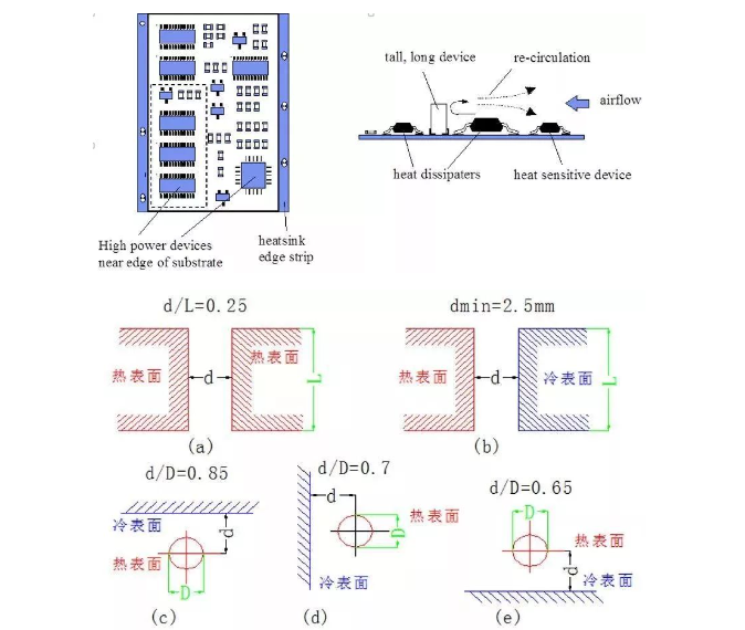
d. Horizontally, high-power devices should be placed as close as possible to the edges of the printed circuit board to shorten the heat transfer path. Vertically, high-power devices should be placed as close as possible to the top of the printed circuit board to minimize the impact of these devices on the temperature of other devices during operation.
e. Heat dissipation from the printed circuit boards within the equipment primarily relies on airflow. Therefore, during design, consider airflow paths and arrange components and printed circuit boards appropriately. Air tends to flow where there is less resistance. Therefore, when placing components on the printed circuit board, avoid leaving large air spaces in certain areas. The same considerations apply to the placement of multiple printed circuit boards within a device.
f. Temperature-sensitive devices are best placed in the lowest temperature areas (such as the bottom of the device). Never place them directly above heat-generating devices. It is best to stagger multiple devices horizontally.
g. Place devices with the highest power consumption and heat generation near the optimal heat dissipation locations. Avoid placing high-heat generating devices in the corners or around the edges of the printed circuit board unless heat dissipation devices are nearby. When designing power resistors, choose larger components whenever possible, and ensure adequate heat dissipation space when adjusting the PCB layout.
h. Component Spacing Recommendations:
2.Adding Heat Sinks or Heat Conductive Plates to High-Heating Components: When a small number of components on a PCB generate significant heat (fewer than three), add a heat sink or heat pipe to the components. If the temperature still cannot be reduced, use a heat sink with a fan to enhance heat dissipation.
When there are a large number of heat-generating components (more than three), a large heatsink (plate) can be used. This is a custom heatsink designed for the location and height of the heat-generating components on the PCB, or it can be cut out of a large flat heatsink to create different heights for the components.
The heatsink is snapped onto the component surface, contacting each component to dissipate heat. However, due to the poor height consistency of the components during soldering, heat dissipation is not effective. Soft, phase-change thermal pads are often added to the component surface to improve heat dissipation.
3.For equipment using free convection air cooling, it is best to arrange integrated circuits (or other devices) in a longitudinal or transverse arrangement.
4.Use a reasonable routing design to achieve heat dissipation. Since the resin in the board has poor thermal conductivity, while copper foil traces and vias are good heat conductors, increasing the copper foil retention ratio and adding thermal vias are the primary means of heat dissipation.
To evaluate the heat dissipation capacity of a PCB, it is necessary to calculate the equivalent thermal conductivity (Eq) of insulating substrates used in PCBs, a composite material composed of various materials with different thermal conductivities.
5.Components on the same printed circuit board should be arranged according to their heat generation and heat dissipation capabilities. Devices with low heat generation or poor heat resistance (such as small-signal transistors, small-scale integrated circuits, electrolytic capacitors, etc.) should be placed upstream (at the inlet) of the cooling airflow, while devices with high heat generation or good heat resistance (such as power transistors, large-scale integrated circuits, etc.) should be placed downstream of the cooling airflow.
6.Horizontally, high-power devices should be placed as close to the edges of the printed circuit board as possible to shorten the heat transfer path. Vertically, high-power devices should be placed as close to the top of the printed circuit board as possible to minimize the impact of these devices on the temperature of other devices during operation.
7.Heat dissipation from the printed circuit boards within the equipment primarily relies on airflow. Therefore, during design, consider the airflow path and arrange the components or printed circuit boards appropriately.
Air tends to flow where there is less resistance. Therefore, when placing components on the printed circuit board, avoid leaving large air spaces in certain areas. The same considerations apply to the placement of multiple printed circuit boards within a device.
8.Temperature-sensitive devices are best placed in the lowest temperature areas (such as the bottom of the device). Never place them directly above heat-generating components. It is best to stagger multiple components horizontally.
9.Place components with the highest power consumption and heat generation near the optimal heat dissipation locations. Avoid placing high-heat generating components in the corners or around the edges of the printed circuit board unless there is a heat sink nearby.
When designing power resistors, choose larger devices whenever possible, and ensure adequate heat dissipation when adjusting the printed circuit board layout.
10.Avoid concentrated hotspots on the PCB. Distribute power as evenly as possible across the PCB to maintain uniform and consistent surface temperature performance.
Achieving a strictly uniform distribution during the design process is often difficult, but areas of excessive power density must be avoided to prevent hotspots that could affect the proper operation of the entire circuit.
If possible, performing a thermal performance analysis of the printed circuit is essential. Thermal performance analysis modules, such as those now included in some professional PCB design software, can help designers optimize circuit designs.