Using Flex-Rigid PCBs Produces More Reliable Products
Expensive and complex discrete interconnect cables can reduce design reliability, increase design cost, and increase overall design size. Fortunately, there is an alternative to flexible and flex-rigid PCBs. Flexible PCBs offer a cost-effective and convenient solution to your design’s interconnect requirements, with the added advantage of increased PCB repeatability and reliability. Discrete interconnects have inherently varying conductor orientations, while flexible PCBs maintain all conductors in a fixed, specific orientation relative to each other. This combined consistency allows for precise modeling of flexible PCB traces and more predictable designs. Additionally, flexible PCBs can include gold finger contacts, allowing the edge of the flexible PCB to function as the male portion of a connector and accommodate high-density designs. Because of this, flexible PCBs can replace the vast majority of traditional discrete interconnect solutions while still allowing for highly modular designs.
In addition to providing an efficient method for producing interconnect solutions for a design, flexible PCBs can also accommodate components and form the foundation of the entire solution. Using flexible PCBs instead of traditional PCBs enables smaller and less conventional PCB designs, capable of fitting into enclosures that otherwise wouldn’t accommodate traditional PCBs. Instead of mounting components on a rigid PCB, you can mount them on the flexible solution, and they will conform to the contours of the enclosure. Furthermore, sections of flexible PCBs can be reinforced with a reinforcing substrate for increased reliability. Finally, flexible PCBs facilitate lightweight solutions, as they have a significantly lower weight per unit area compared to traditional PCBs. Examples of applications commonly based on flexible PCB solutions include wearables, digital cameras, medical devices, and other small consumer electronics.
Flexible PCBs also offer the advantage of inherent vibration resistance. They are often used in automotive equipment due to their inherent vibration resistance and are also well-suited for electronic devices with mechanical components. Consequently, they are widely used in printers, hard drives, and keyboards.
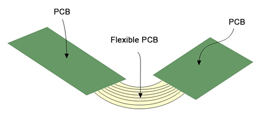
Flex-rigid PCBs are the perfect match between traditional PCBs and flexible solutions. They utilize a flex-rigid design with built-in interconnects between the two boards. Using flex-rigid solutions allows designers to incorporate three-dimensional solutions in a single assembly step. Using flex-rigid PCBs instead of traditional PCBs and discrete connections can shorten the assembly time of the final product and ultimately result in a more reliable product. The growth in the use of flex-rigid solutions in recent years demonstrates the practicality they offer.
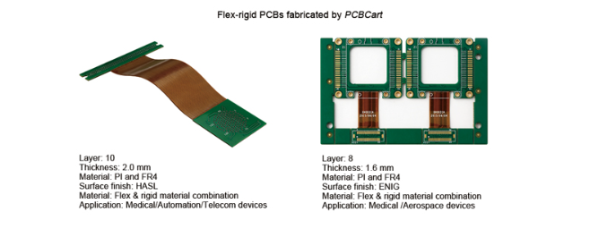
Below are two flex-rigid PCB samples manufactured by PCBCart:
The design process for flexible or rigid solutions is very similar to that for traditional PCBs, but it’s important to note that the flexible portion of the board requires special attention to mechanical quality. Once a 2D layout of the flexible design is created, it’s best to create a simulation of the flexible design using 3D modeling software or a paper simulation of the design. This method allows you to test whether the design meets the mechanical specifications of the flexible substrate. Furthermore, your design doesn’t need to have a bend radius smaller than that allowed by the flexible PCB. You can refer to IPC-2223 to determine the minimum bend radius for a specific design.
Other design tips include: Consider staggering traces from one layer to another on the flexible circuit to provide a higher level of flexibility. Conductors should always be routed perpendicular to the bend radius to improve reliability and flexibility. Termination areas should be reinforced with stiffeners. Shielding should use a cross-hatch pattern rather than a solid plane. Vias should be placed away from bend areas.
Before sending your design for manufacturing, consider designing for flexible PCBs that are bendable during the design process and design the boards for maximum density when nested on the fabricated board. If bending can be used to achieve a specific dimension, implement the bending during installation rather than in the initial design. Finally, using stiffeners with a flexible PCB may be more cost-effective than a flex-rigid design. When your design requires only a small number of layers, using a flexible PCB and adding stiffeners in critical sections of the board may be more cost-effective. Only consider a flexible-rigid solution if your design has a very high layer count requirement.
Finally, populating a flexible PCB is very similar to populating a rigid PCB. When assembling a flexible PCB, consider the following tips:
- Bake the flexible PCBs for one hour before populating them to eliminate any absorbed moisture.
- Secure the flexible PCB to a hard surface to provide dimensional stability when soldering to the device.
- When hand-soldering devices to the flexible PCB, skip soldering densely secured devices to avoid overheating sections of the flex PCB.
In summary, flexible and flex-rigid PCBs can significantly reduce the cost and complexity of the manufacturing process for your next product. Flexible PCBs are an excellent alternative to traditional discrete wiring solutions, offering the repeatability and reliability of PCBs in a flexible form factor. Furthermore, flex-rigid PCBs offer the opportunity to create highly complex three-dimensional designs while maintaining low assembly costs and high levels of repeatability and reliability. In short, flexible PCBs allow you to tackle designs that would otherwise be too costly, complex to manufacture, or simply impossible. Take your designs to the next level with flexible or flex-rigid PCBs.