
PCB Countersink and Counterbore: Design for Flush Mounting
When your PCB assembly requires flush-mounted hardware, choosing between countersink and counterbore holes directly impacts mechanical strength, manufacturing cost, and assembly reliability. We’ve seen product launches delayed because designers specified 82° countersinks without verifying their fab’s tooling—the boards came back with 90° angles that didn’t match the hardware.
Countersink vs Counterbore: Core Differences
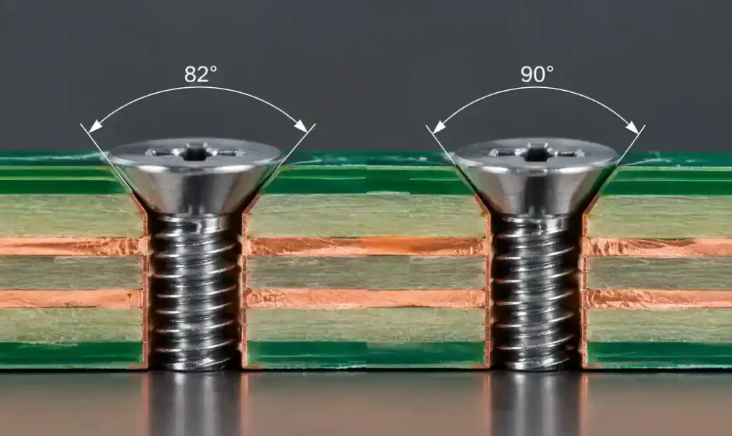
A countersink creates a cone-shaped depression machined into the PCB surface. The tapered geometry matches flat-head screw profiles, allowing the fastener to sit flush with or below the board surface. Standard angles include 82° (ANSI), 90° (ISO), and 100° (specialty applications). The conical profile means material removal increases exponentially with depth.
A counterbore produces a flat-bottomed cylindrical recess that accommodates socket-head cap screws, pan-head screws with washers, or any fastener requiring a flat seating surface. Counterbores remove less material than equivalent countersinks because the recess diameter remains constant through depth.
| Feature | Countersink | Counterbore |
|---|---|---|
| Geometry | Conical taper | Flat-bottomed cylinder |
| Compatible fasteners | Flat-head screws (82°, 90°) | Socket-head, pan-head, button-head |
| Material removal | Increases with depth² | Linear with depth |
| Depth control precision | ±0.10-0.15mm typical | ±0.05-0.10mm achievable |
| Minimum board thickness | 1.6mm recommended | 1.0mm possible |
| Cost vs standard hole | 1.3-1.8× | 1.2-1.5× |
| Feature | Countersink | Counterbore |
|---|---|---|
| Geometry | Conical taper | Flat-bottomed cylinder |
| Compatible fasteners | Flat-head screws (82°, 90°) | Socket-head, pan-head, button-head |
| Material removal | Increases with depth² | Linear with depth |
| Depth control precision | ±0.10-0.15mm typical | ±0.05-0.10mm achievable |
| Minimum board thickness | 1.6mm (for shallow countersinks) | 1.0mm (counterbore depth dependent) |
| Cost multiplier vs standard hole | 1.3-1.8× | 1.2-1.5× |
When to Use Each Type
Choose countersinks when your enclosure design demands flat-head screws and you have adequate board thickness. For thin enclosures, flat-head screws in countersunk holes provide the lowest profile—an M3 flat-head screw adds only 0.2-0.3mm above the board versus 2.0mm for socket-head alternatives. Consumer products often specify flush hardware for clean industrial design. If your CM already uses flat-head screws, matching that hardware reduces BOM cost 15-25%.
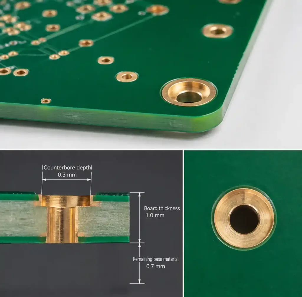
Counterbores work better when you need controlled fastener seating or have limited board thickness. Socket-head cap screws in counterbored holes deliver 40-60% higher clamp force than flat-head screws of equivalent diameter, preventing fastener loosening under thermal cycling. Boards <1.2mm thick cannot safely accommodate deep countersinks—a 1.0mm rigid-flex PCB can use a 1.5mm deep counterbore for M2.5 socket-head screws. Counterbores also provide flat surfaces for load-distributing washers that prevent stress cracking.
Design Specifications and Tolerances
Countersink depth must account for screw head height, board thickness tolerance, and machining precision. The formula is: Depth = (Screw head diameter – Pilot hole diameter) / (2 × tan(θ/2)) + Flush tolerance.
For an M3 flat-head screw (head diameter 5.5mm, 82° angle) in a 3.2mm pilot hole: Depth = (5.5 – 3.2) / (2 × tan(41°)) = 1.32mm. Add 0.15mm flush tolerance to specify 1.5mm depth ensuring the head sits 0.1-0.2mm below surface after board thickness variation.
Counterbore depth equals screw head height plus flush clearance. For an M3 socket-head cap screw (head height 3.0mm, head diameter 5.5mm): counterbore diameter 6.0mm (5.5 + 0.5mm clearance), counterbore depth 3.2mm (3.0 + 0.2mm clearance), pilot hole 3.3mm. Depth tolerance of ±0.10mm is achievable with CNC routing, ±0.15mm with manual tools.
| Board Thickness | Max Countersink Depth | Max Counterbore Depth |
|---|---|---|
| 0.8mm | 0.4mm (50%) | 0.6mm (75%) |
| 1.0mm | 0.5mm (50%) | 0.7mm (70%) |
| 1.2mm | 0.6mm (50%) | 0.9mm (75%) |
| 1.6mm | 0.8mm (50%) | 1.2mm (75%) |
| 2.0mm | 1.2mm (60%) | 1.6mm (80%) |
These percentages represent remaining material after machining. Stay below 50% removal for countersinks; counterbores can safely reach 75% because cylindrical geometry distributes stress more evenly.
| Board Thickness | Max Recommended Countersink Depth | Max Recommended Counterbore Depth |
|---|---|---|
| 0.8mm | 0.4mm (50%) | 0.6mm (75%) |
| 1.0mm | 0.5mm (50%) | 0.7mm (70%) |
| 1.2mm | 0.6mm (50%) | 0.9mm (75%) |
| 1.6mm | 0.8mm (50%) | 1.2mm (75%) |
| 2.0mm | 1.2mm (60%) | 1.6mm (80%) |
These percentages represent remaining material after machining. Stay below 50% removal for countersinks to preserve mechanical strength; counterbores can safely go to 75% because the cylindrical geometry distributes stress more evenly.
Minimum Material and Copper Clearance Requirements
Both features require adequate material above inner copper layers. Breaking through power or ground planes creates EMI issues and weakens the board. Maintain 0.3mm (12 mils) minimum between the machined feature and nearest inner copper layer. For a 4-layer 1.6mm board with standard stackup, countersink from top should not exceed 0.5mm depth, while counterbores can go to 0.8mm.
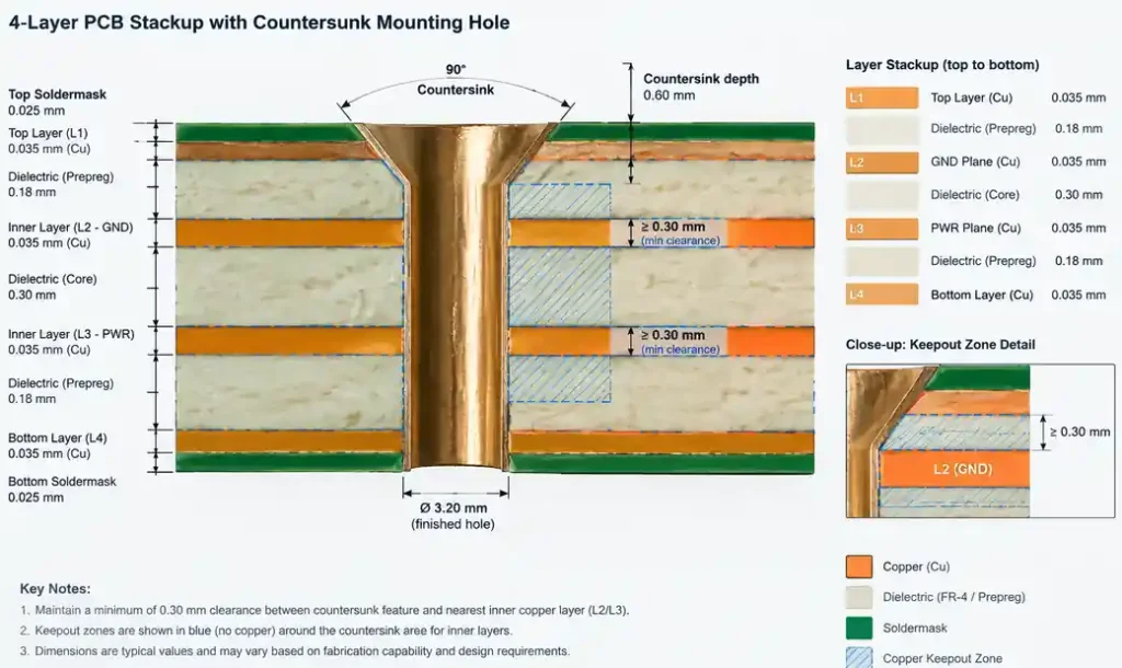
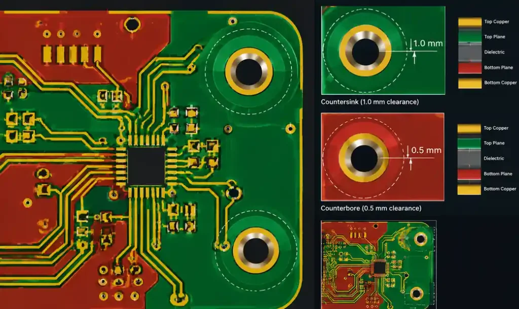
Define keepout areas around holes to prevent copper exposure during machining. Standard practice: countersink keepout = feature diameter + 1.0mm radial clearance; counterbore keepout = feature diameter + 0.5mm clearance. For HDI PCBs with thin dielectric layers (0.1-0.15mm), countersinks become impractical—use counterbores or surface-mount standoffs.
Mounting Hardware Compatibility
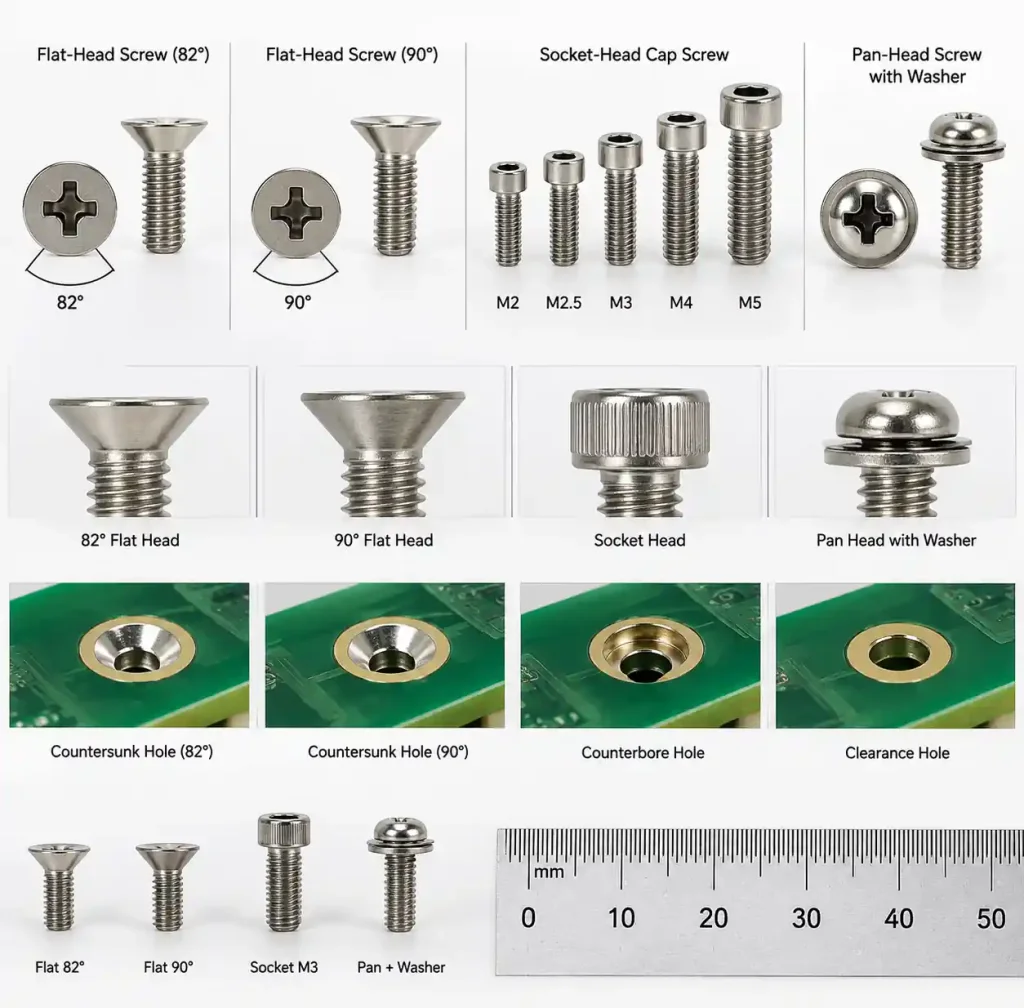
Fastener specifications must match machined features within 0.1mm for reliable flush mounting. Common flat-head screw standards include ISO 7046 (90° angle), ISO 2009/DIN 963 (90°), and ASME B18.6.7 (82°). Chinese domestic screws often use 90° even when marked “M3.” If you design for 82° countersinks and your CM sources 90° hardware, every screw sits 0.3-0.5mm proud. Specify both angle and standard in your BOM.
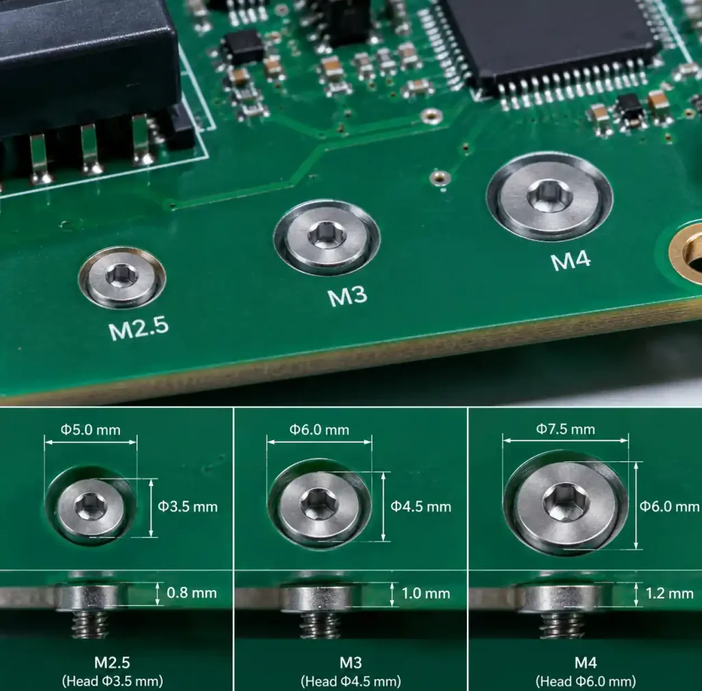
Socket-head cap screws follow ISO 4762 (metric) or ASME B18.3 (inch) with ±0.1mm head diameter tolerance. Add 0.6mm diameter clearance for assembly tolerance and 0.3mm depth margin for flush seating.
| Screw Size | Head Diameter | Head Height | Counterbore Ø | Counterbore Depth |
|---|---|---|---|---|
| M2 | 3.8mm | 2.0mm | 4.4mm | 2.3mm |
| M2.5 | 4.5mm | 2.5mm | 5.1mm | 2.8mm |
| M3 | 5.5mm | 3.0mm | 6.1mm | 3.3mm |
| M4 | 7.0mm | 4.0mm | 7.6mm | 4.3mm |
| M5 | 8.5mm | 5.0mm | 9.2mm | 5.3mm |
Manufacturing Process and Quality Control
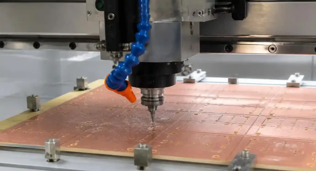
PCB fabs use three methods with different cost and precision trade-offs. CNC routing achieves ±0.10mm diameter and ±0.15mm depth tolerance, adding 30-50% cost. Manual countersinking for <50 boards degrades to ±0.20mm depth. Form-countersink drill bits for 500-1000+ piece orders improve tolerances to ±0.08mm, suitable for automotive PCBs.
Depth verification requires more than visual inspection. Use depth gauge measurement for samples, optical profilometry for medical device PCBs, or go/no-go gauging for 100% production inspection. Your fab should provide depth data for first articles—if they claim visual inspection only, find another vendor.
Cost and Design Optimization
Countersinking and counterboring add 25-60% to hole drilling cost. For 1000-piece orders on 1.6mm FR-4: 4× standard holes cost $0.08/board, 4× countersunk holes cost $0.12/board (+50%), 4× counterbored holes cost $0.11/board (+37%). The premium drops to 15-20% at 10,000+ volumes.
Hidden costs include non-standard angles (+30%), tight tolerances at ±0.05mm (+40-60%), and mixed features (+20% programming). Standardize hardware across product lines to reuse tooling and reduce setup time 40-50%. Question whether you need special features—standard through-holes with low-profile pan-head screws often suffice and cost 50% less. Panelize by grouping features to avoid tool changes.
Common Design Mistakes
Insufficient remaining material: Specifying 1.2mm countersink depth in 1.6mm board leaves only 0.4mm base material. First thermal cycle cracks the board around mounting holes. Follow the 50% rule for countersinks, 75% rule for counterbores. If you need deeper features, increase board thickness or switch to metal core PCB.
Angle mismatches: Designing 90° countersink while hardware supplier delivers 82° screws creates 0.4mm gaps between screw head and board surface. Specify both angle AND standard (ISO/ASME) in BOM and request screw samples before finalizing PCB design.
Inadequate copper clearance: Counterbore machining exposing inner ground plane causes hipot failures and EMI radiation. Define keepout zones: countersink keepout = diameter + 1.0mm, counterbore keepout = diameter + 0.5mm. For high-voltage PCBs, double these clearances.
Over-specifying tolerances: Copying ±0.03mm depth tolerance from precision machining standards causes 3× normal price or order rejection. ±0.10mm handles 95% of applications. Only tighten to ±0.05mm for optical systems, medical devices, or where flush mounting affects product function. Each 0.05mm tighter adds 30-50% cost.
FAQ
Q: Can I add countersinks to flexible PCBs?
A: Not recommended. Flex circuits are typically 0.1-0.2mm thick—countersinking removes >50% of material and creates stress concentration that cracks during flexing. Use surface-mount standoffs or bondable fasteners. For rigid-flex designs, place countersinks only in rigid sections.
Q: How deep can I countersink a 1.6mm board?
A: Maximum 0.8mm (50% of thickness) to maintain structural integrity. This accommodates M3 flat-head screws at 82°. For M4 or larger, switch to counterbores or increase board thickness to 2.0mm.
Q: What’s the minimum PCB thickness for a 3mm deep counterbore?
A: 4.0mm following the 75% rule (3.0mm / 0.75 = 4.0mm). Thinner boards risk delamination under fastener load. If using 1.6mm material, reduce counterbore depth to 1.2mm and use low-profile socket-head screws.
Q: Do counterbores cost more than countersinks?
A: Counterbores typically cost 10-20% less because depth control is easier and tooling is simpler. CNC routers complete counterbores faster, reducing machine time.
Q: How do I specify countersink angle in Gerber files?
A: Gerber X2 supports countersink attributes via aperture definition. For older CAM systems, add a mechanical drawing layer with cross-section views showing angle, depth, and diameter. Many fabs still require PDF drawings.
Q: Can I countersink plated holes?
A: Yes, but the countersink removes plating on the conical surface—only the pilot hole remains plated. This is standard for mounting holes needing electrical grounding. Specify plating after drilling, countersinking before plating.
Conclusion
Countersinks and counterbores are not interchangeable—selecting the wrong feature costs you in rework, assembly delays, and warranty returns. Match your choice to fastener type, board thickness, and assembly requirements. Verify your fab’s capabilities early and specify tolerances based on functional needs.
For low-profile assemblies under 10mm height, countersinks with flat-head screws deliver the smallest footprint. When torque matters or boards are thin, counterbores with socket-head fasteners provide superior mechanical performance. Leave adequate base material and maintain proper copper clearance to prevent structural and electrical failures. Start with hardware selection, calculate feature dimensions with margin, verify against minimum material rules, and communicate specifications clearly in fabrication drawings and BOM.