
Polyimide PCB: High-Temperature Flex and Rigid Boards
When automotive radar modules survive thermal shock from -40°C to +150°C in engine compartments, or satellite PCBs operate reliably for 15 years in space, polyimide substrates make that durability possible. Polyimide isn’t FR4’s more expensive cousin—it’s a fundamentally different material engineered for environments where standard epoxy-glass laminates fail.
Polyimide costs 3-5 times more than FR4, but delivers capabilities FR4 cannot: glass transition temperatures exceeding 250°C, dimensional stability through thousands of thermal cycles, and mechanical flexibility for repeated bending.
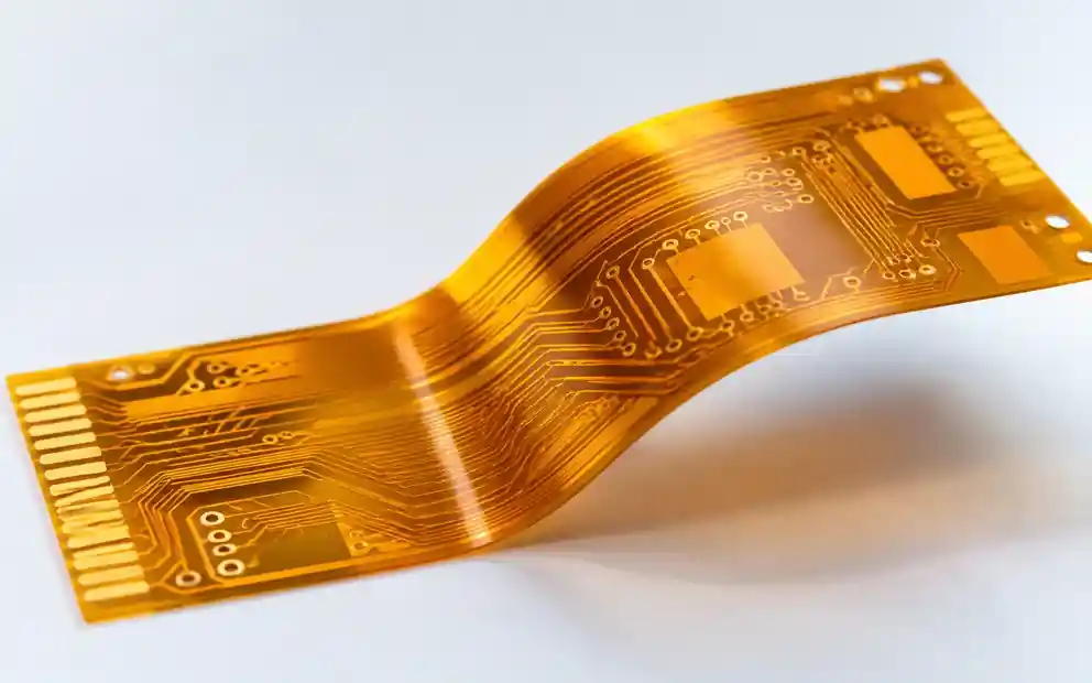
Polyimide Material Properties vs FR4
Polyimide’s molecular structure—aromatic rings linked by imide bonds—creates thermal and mechanical properties that separate it from FR4’s woven glass-epoxy composite.
Thermal Performance
The glass transition temperature (Tg) for polyimide ranges from 360°C to 410°C, compared to FR4’s 130-170°C. Continuous operating temperature for polyimide reaches 260°C versus FR4’s 130°C maximum. This allows polyimide PCBs to function in engine bays, downhole drilling tools, and high-power LED applications where FR4 would fail.
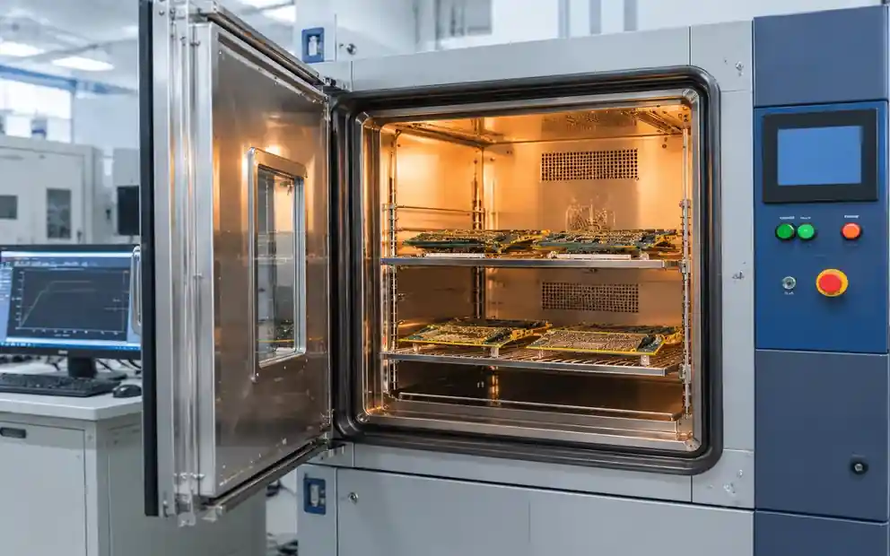
Mechanical and Dimensional Stability
Polyimide films withstand over 100,000 bend cycles at 3mm radius—essential for medical devices, wearables, and articulating assemblies. Coefficient of thermal expansion (CTE) for polyimide measures 12-16 ppm/°C, closer to copper’s 17 ppm/°C than FR4. This CTE matching reduces stress during thermal cycling, critical for aerospace applications requiring 1,000+ cycles from -55°C to +125°C.
| Property | Polyimide | FR4 (Tg 170°C) | Significance |
|---|---|---|---|
| Glass Transition Temp (Tg) | 360-410°C | 130-170°C | Thermal stability limit |
| Continuous Operating Temp | 260°C | 130°C | Long-term reliability ceiling |
| Tensile Strength | 165-310 MPa | 70-140 MPa | Mechanical durability |
| CTE (in-plane) | 12-16 ppm/°C | 14-17 ppm/°C | Thermal cycling reliability |
| Dielectric Constant (1 MHz) | 3.2-3.5 | 4.2-4.8 | RF performance |
| Dissipation Factor (1 MHz) | 0.002-0.005 | 0.015-0.025 | Signal loss |
Polyimide PCB Types and Configurations
Flexible Polyimide PCB
Single and multilayer flex PCBs use polyimide films from 12.5 to 125 microns thick. DuPont’s Kapton remains the industry standard. Flexible circuits tolerate bend radii as tight as 10× total thickness for static installations, or 20× for dynamic flex applications. This makes polyimide essential for medical endoscopes, wearables, and articulating electronics.
Rigid Polyimide PCB
Rigid polyimide laminates combine polyimide resin with glass reinforcement, creating boards with FR4’s rigidity while retaining polyimide’s thermal performance. Aerospace applications favor rigid polyimide for avionics and satellites where temperatures exceed FR4’s capabilities. Material costs run 4-6× FR4 but deliver reliability where replacement is impossible.
Rigid-Flex Polyimide Constructions
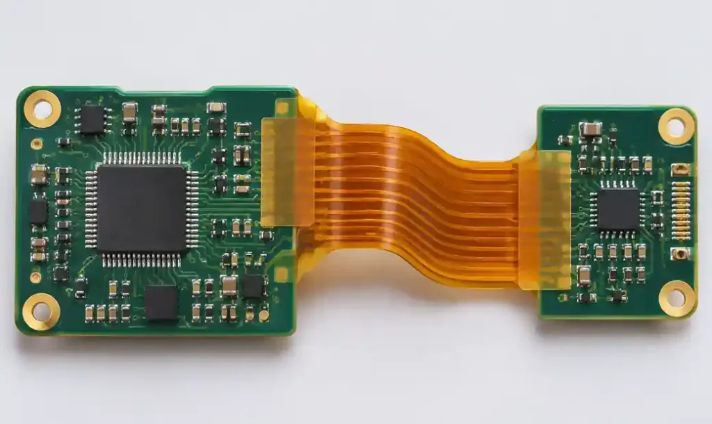
Rigid-flex PCBs combine rigid sections with flexible polyimide interconnects, eliminating connectors and reducing assembly complexity. Sequential lamination bonds rigid sections to flexible cores, requiring precise registration control due to CTE mismatch between materials. Designs must incorporate stress relief features to prevent delamination.
Polyimide vs Rogers for RF Applications
High-frequency designers compare polyimide to Rogers laminates for RF and microwave applications above 1 GHz. Rogers RO4350B offers tighter dielectric constant control (Dk 3.48) and lower dissipation factor (Df 0.0037) than polyimide, making it preferable for 5G infrastructure, 77 GHz automotive radar, and satellite communications where signal loss is critical.
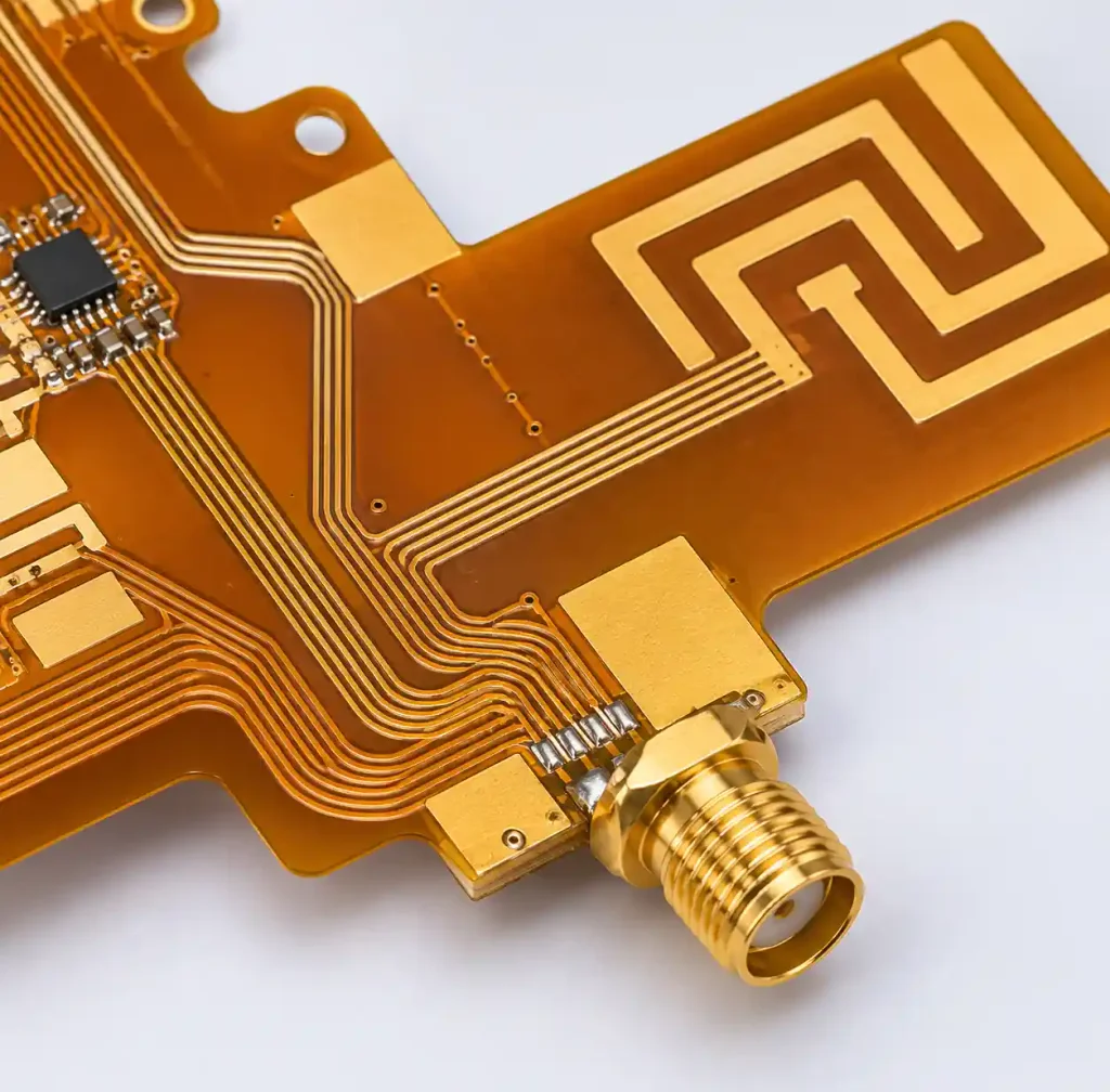
Polyimide wins when designs require mechanical flexibility Rogers’ ceramic-PTFE construction cannot provide, or when sustained temperatures exceed 200°C. Flexible antenna arrays, conformal radar installations, and deployable space structures combine RF performance with mechanical constraints only polyimide satisfies.
| Parameter | Polyimide (Flex) | Rogers RO4350B | Application Fit |
|---|---|---|---|
| Dielectric Constant (10 GHz) | 3.2-3.5 | 3.48 | Rogers tighter tolerance |
| Dissipation Factor (10 GHz) | 0.002-0.005 | 0.0037 | Comparable RF loss |
| Flexibility | High (3mm bend radius) | Rigid (no flex) | Polyimide for flex designs |
| Max Operating Temp | 260°C continuous | 280°C max | Polyimide for sustained heat |
| Cost Multiplier vs FR4 | 3-5× | 4-7× | Similar premium tier |
Design Considerations for Polyimide PCBs
Copper Selection and Adhesion
Polyimide uses rolled-annealed (RA) or electrodeposited (ED) copper. RA copper offers better flexibility for dynamic flex because its grain structure resists fatigue cracking. Adhesiveless copper-clad films use plasma treatment to bond copper directly, withstanding temperatures up to 400°C during lead-free soldering but requiring careful handling.
Feature Sizes and Registration
Polyimide achieves 75-micron (3 mil) traces and spaces in production flex circuits versus FR4’s 100-micron minimum. Layer-to-layer registration holds ±50 microns across 300mm panels, compared to FR4’s ±75 micron capability. This accuracy matters for blind and buried via designs where misalignment causes capture pad violations.
Bend Radius and Stress Relief
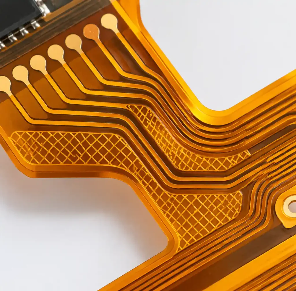
Dynamic flex applications need minimum 20× bend radius relative to total thickness. Static flex tolerates 10× thickness. A 68-micron two-layer flex circuit requires 1.4mm bend radius for dynamic applications. Stress relief features—hatched copper fills, teardrop connections, and proper stiffener placement—prevent copper cracking in flex zones.
Common Applications by Industry
Aerospace and Defense
Satellites, avionics, and military systems require thermal cycling from -55°C to +125°C and radiation tolerance. Polyimide’s low outgassing (NASA ASTM E595 compliant) prevents contamination of optical instruments. 15-25 year mission lifespans eliminate FR4 because it cannot survive thermal cycling and radiation without delamination.
Automotive Under-Hood Electronics
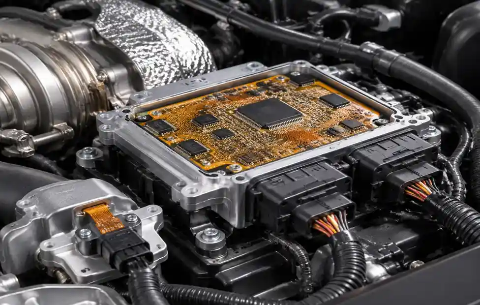
Engine control units and turbocharger electronics operate at 150-175°C ambient with peaks to 200°C. Automotive PCBs using polyimide pass AEC-Q100 Grade 0 qualification (-40°C to +150°C) with lifespans beyond 100,000 engine hours.
High-Power LED and Medical Implantables
LED driver circuits generate significant heat. Polyimide provides thermal stability for maintaining LED alignment over 50,000+ hours. Medical pacemakers and neural stimulators use flexible polyimide for ISO 10993 biocompatibility and long-term stability in body fluids through sterilization processes.
Manufacturing Process Differences
Manufacturing Process Differences
Lamination and Drilling
Polyimide films lack glass-reinforced FR4’s dimensional stability during lamination. Manufacturers use mechanical fixtures during press cycles. Sequential lamination builds multilayer constructions one layer at a time, improving registration but increasing process time and cost.
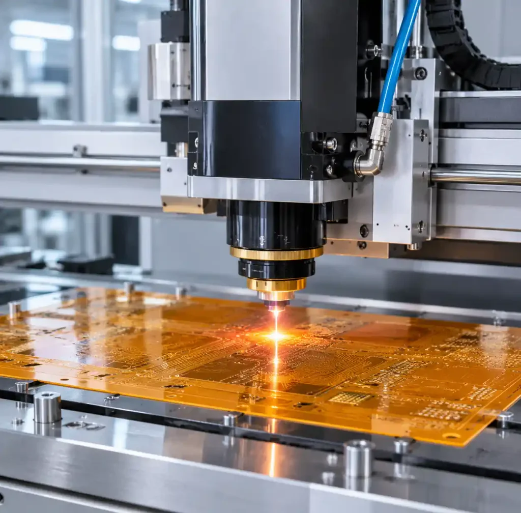
Polyimide’s toughness creates more drill bit wear—carbide or diamond-coated bits extend tool life. Laser drilling works well for HDI microvias. Laser cutting forms flex outlines more precisely than die punching.
Cost Analysis and When Polyimide Justifies Premium
Polyimide PCBs cost 3-5× FR4 equivalents. Rigid-flex constructions run 4-6× rigid FR4 costs. This premium makes sense when operating temperatures continuously exceed 150°C, applications require 1,000+ thermal cycles across 100°C spans, mechanical flexibility is essential, product lifespans extend beyond 10 years in harsh environments, or field failure costs far exceed the material premium.
For applications below 130°C without flex requirements, high-Tg FR4 delivers adequate performance at significantly lower cost.
FAQ
What is the typical glass transition temperature (Tg) of polyimide PCB materials?
Polyimide films exhibit Tg from 360°C to 410°C, which is 200-250°C higher than FR4’s 130-170°C. This allows polyimide to maintain properties at temperatures that cause FR4 to soften and delaminate.
How does polyimide compare to FR4 for high-temperature applications?
Polyimide operates continuously at 260°C versus FR4’s 130°C maximum. The cost trade-off is 3-5× higher expenses, justified when thermal requirements exceed 150°C or applications demand 1,000+ thermal cycles.
Can polyimide PCBs be used for rigid board applications?
Yes, rigid polyimide laminates combine polyimide resin with glass reinforcement for thermal performance superior to FR4. These boards cost 4-6× more but deliver reliability in -55°C to +125°C thermal cycling.
What are the main advantages of polyimide for flexible circuits?
Polyimide withstands 100,000+ bend cycles while maintaining electrical performance, making it ideal for medical devices, wearables, and articulating assemblies. The combination of flexibility, 260°C tolerance, and low moisture absorption surpasses PET.
How many bend cycles can polyimide flex circuits withstand?
Dynamic flex using rolled-annealed copper achieves 100,000+ bend cycles at 3mm radius. Static flex tolerates tighter 10× total thickness radii. Cycle life depends on bend radius, copper thickness, and copper type.
Is polyimide suitable for RF and high-frequency PCB designs?
Polyimide’s dielectric constant (3.2-3.5 at 10 GHz) provides adequate RF performance. Rogers laminates offer tighter tolerances for critical RF, but polyimide wins when designs require flexibility or temperatures exceed 200°C.
Conclusion
Polyimide PCB materials deliver thermal and mechanical performance unattainable with FR4, justifying 3-5× cost premiums when applications genuinely demand their capabilities. With Tg above 360°C, continuous operation to 260°C, and 100,000+ bend cycle flexibility, polyimide solves engineering problems in aerospace, automotive, medical, and high-power electronics.
The decision hinges on matching material costs to actual requirements. Applications below 150°C without flex needs rarely justify polyimide’s premium—high-Tg FR4 typically suffices. When thermal cycling exceeds 1,000 cycles across 100°C spans, temperatures approach 175°C, or designs require flexibility, polyimide becomes practical despite higher costs.
High-temperature PCB applications requiring 15-25 year lifespans benefit from early material selection with your fabricator. For projects pushing FR4’s limits, Andwin Circuits’ polyimide PCB capabilities cover flexible and rigid constructions with proven aerospace and automotive performance.