
Rogers PCB Material: RO4003C vs RO4350B for RF and Microwave
For 5G base stations, automotive radar, and satellite communications operating above 10GHz, RO4003C delivers 27% lower loss (Df 0.0027 vs 0.0037) than RO4350B at a similar price point, making it optimal for long-distance signal transmission and low-noise amplifier designs. RO4350B offers higher thermal conductivity (0.69 vs 0.64 W/m·K) and better processing compatibility with lead-free assembly, making it the preferred choice for high-power RF amplifiers, phased array antennas, and mixed-technology boards where standard FR-4 processing equipment reduces manufacturing cost.
Both materials use Rogers’ proven hydrocarbon/ceramic composite technology with glass reinforcement, enabling conventional PCB fabrication without the specialized handling required for PTFE-based laminates. If you need to minimize insertion loss for receiver chains, specify RO4003C. If thermal dissipation and ease of manufacturing matter more than the last 0.3dB of loss, choose RO4350B.
What Are Rogers RO4003C and RO4350B Materials?
Rogers RO4003C and RO4350B are woven glass-reinforced hydrocarbon/ceramic laminates engineered for RF and microwave PCB applications from 500MHz to 40GHz. Unlike PTFE materials that require specialized drilling and chemical etching, both RO4003C and RO4350B process using standard FR-4 fabrication equipment—reducing manufacturing cost by 40-60% compared to RT/duroid 5880 while delivering far superior electrical performance than FR-4.
The materials share identical glass transition temperature (Tg >280°C), coefficient of thermal expansion (CTE), and Z-axis expansion characteristics, ensuring reliability through multiple lead-free reflow cycles at 260°C. This thermal stability eliminates the via barrel cracking and delamination issues common in standard FR-4 multilayer boards subjected to automotive qualification testing (AEC-Q100) or military temperature cycling (MIL-STD-810).
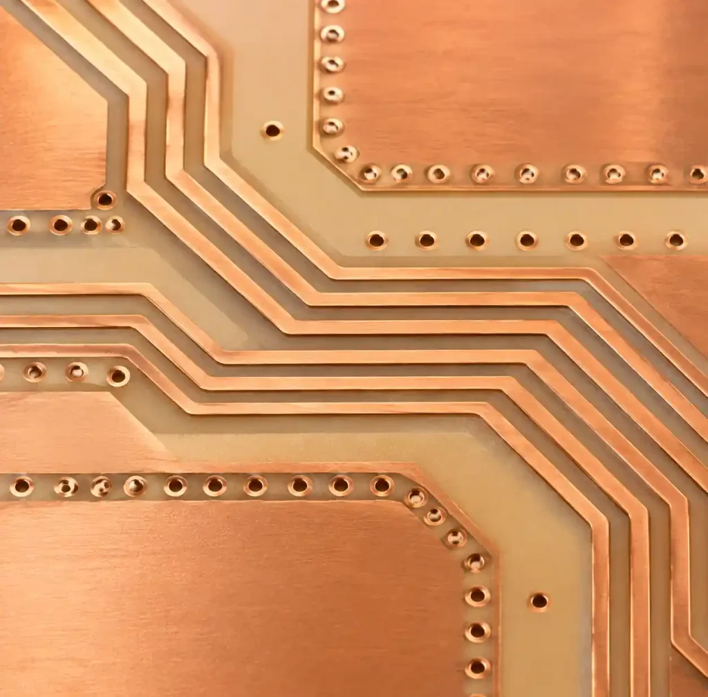
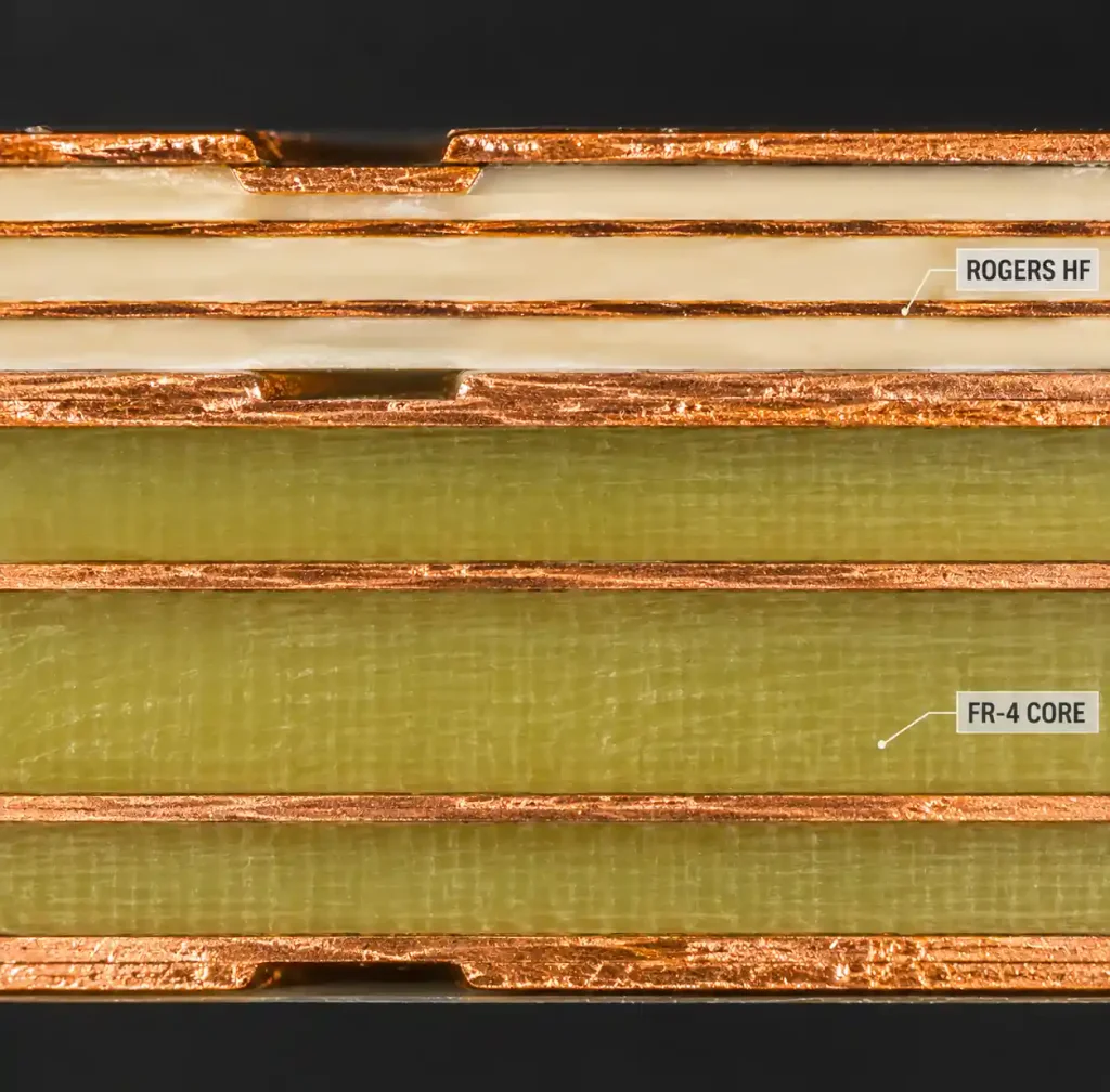
You can use these materials for HDI PCB designs with blind and buried vias, mixed dielectric stackups pairing Rogers with FR-4 core layers, and hybrid constructions where RF sections use Rogers material while digital sections use cost-effective FR-4.
RO4003C vs RO4350B: Key Electrical Properties Comparison
| Property | RO4003C | RO4350B | Impact on Design |
|---|---|---|---|
| Dielectric Constant (Dk) @ 10GHz | 3.38 ± 0.05 | 3.48 ± 0.05 | RO4003C enables narrower 50Ω traces, saving board space in dense layouts |
| Dissipation Factor (Df) @ 10GHz | 0.0027 | 0.0037 | RO4003C provides 27% lower loss—critical for low-noise amplifiers and long transmission lines |
| Thermal Coefficient of Dk | +40 ppm/°C | +50 ppm/°C | RO4003C delivers better frequency stability across -40°C to +85°C automotive range |
| Thermal Conductivity (Z-axis) | 0.64 W/m·K | 0.69 W/m·K | RO4350B dissipates heat 8% better for high-power amplifiers |
| Design Dk Value | 3.55 | 3.66 | Use design Dk for impedance calculation; process Dk for measurement correlation |
Dielectric Constant and Impedance Control
The 0.10 difference in process Dk between RO4003C (3.38) and RO4350B (3.48) translates to 5-7% narrower trace widths for RO4003C when targeting 50Ω single-ended impedance on identical stackups. For a 10-mil thick dielectric, 50Ω microstrip width calculates to approximately 18 mils on RO4003C versus 19 mils on RO4350B.
This difference matters in miniaturized RF modules where board area costs $0.50-2.00 per square inch. Tighter routing on RO4003C enables smaller board dimensions or additional circuit density. The tighter Dk tolerance (±0.05) ensures impedance variation stays within ±5-7% across production lots without trim tuning.
Loss Tangent and Signal Integrity
RO4003C’s dissipation factor of 0.0027 versus RO4350B’s 0.0037 produces measurably lower insertion loss at microwave frequencies. At 28GHz (5G FR2 band), a 4-inch microstrip transmission line on RO4003C exhibits approximately 0.4dB less loss than the same line on RO4350B. This 0.4dB difference accumulates across multi-stage amplifier chains, antenna feed networks, and long backplane traces.
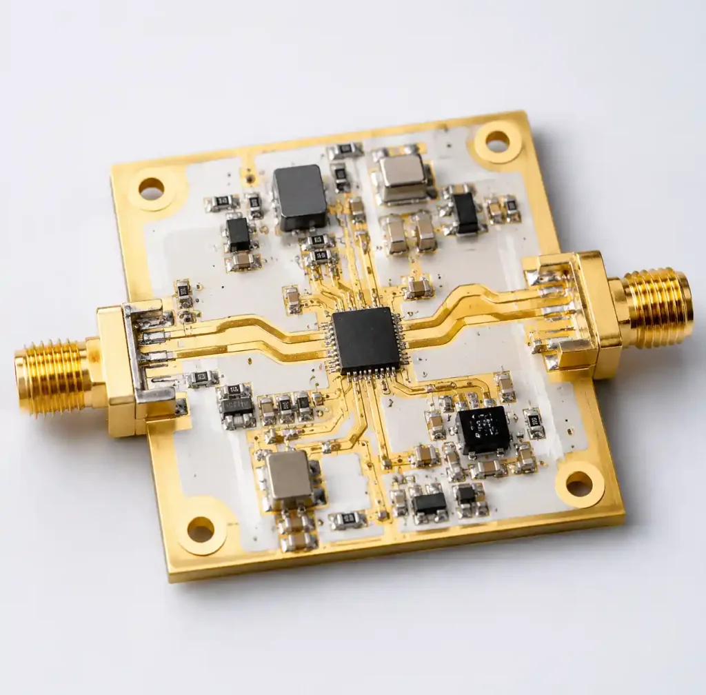
For low-noise amplifier (LNA) designs where every 0.1dB of noise figure matters, RO4003C’s lower loss directly improves system sensitivity. Satellite downlink receivers, radar front-ends, and 5G massive MIMO arrays benefit from this performance advantage. Conversely, high-power amplifiers dissipating 10-50W see minimal benefit from RO4003C’s loss advantage but gain significantly from RO4350B’s superior thermal conductivity.
Thermal Performance and High-Power Applications
| Thermal Property | RO4003C | RO4350B | Application Guidance |
|---|---|---|---|
| Thermal Conductivity | 0.64 W/m·K | 0.69 W/m·K | RO4350B recommended for >5W RF power devices |
| Glass Transition (Tg) | >280°C | >280°C | Both survive 260°C lead-free reflow (6-8 cycles) |
| CTE (X/Y-axis) | 11 ppm/°C | 11 ppm/°C | Identical expansion prevents via barrel stress |
| CTE (Z-axis, <Tg) | 46 ppm/°C | 46 ppm/°C | Low Z-expansion critical for plated through-holes |
| Decomposition Temperature (Td) | >425°C | >425°C | Both meet automotive and aerospace thermal requirements |
RO4350B’s 0.69 W/m·K thermal conductivity provides 8% better heat spreading than RO4003C’s 0.64 W/m·K. For RF power amplifiers operating at 10W output and 40% power-added efficiency (PAE), the device dissipates 15W as heat. This 8% thermal conductivity improvement translates to 2-4°C lower junction temperature when combined with proper copper pour and thermal via design.
High-power applications include 5G massive MIMO power amplifiers, radar transmitters, satellite uplink amplifiers, and broadcast transmitters. These designs typically integrate copper-filled thermal vias under power devices and use metal core PCB techniques for extreme power density. For receiver paths, LNA stages, and passive distribution networks under 2W dissipation, RO4003C’s thermal performance proves more than adequate.
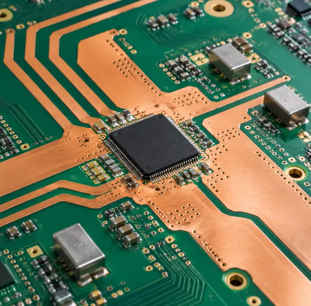
Manufacturing Compatibility and Processability
Both RO4003C and RO4350B were engineered specifically to process using standard FR-4 manufacturing equipment, eliminating the specialized handling required for PTFE materials. This compatibility reduces fabrication cost and lead time while expanding the supplier base beyond specialized RF PCB manufacturers.
Standard Processing Compatibility:
- Mechanical drilling using carbide or diamond-coated bits (no sodium naphthalate etch required)
- Conventional through-hole plating without plasma treatment
- Standard photoimaging and wet etching (no sodium etch for copper removal)
- Hot-air solder leveling (HASL) and lead-free surface finishes (ENIG, immersion silver, OSP)
- Automated optical inspection (AOI) without specialized handling
RO4350B exhibits slightly easier processing than RO4003C due to its resin system formulation. RO4350B’s higher resin content reduces drill bit wear by approximately 15-20% and improves routing edge quality. Some manufacturers report that RO4350B demonstrates better dimensional stability during large panel processing (18×24 inch) compared to RO4003C, though both materials meet IPC-4101 /126 specification requirements.
Lead-free assembly at 260°C peak reflow temperature subjects PCBs to significant thermal stress. Both materials survive 6-8 reflow cycles without measurable degradation in electrical properties or mechanical integrity, making them suitable for complex PCB assembly processes including component rework.

Frequency Range and Application Selection
5G Infrastructure (Sub-6GHz and mmWave)
For 5G sub-6GHz base stations operating at 3.3-4.2GHz, both materials work well. RO4003C’s lower loss provides marginal advantage (0.1-0.2dB per 4-inch trace) that matters in sensitive receiver paths. For 5G FR2 mmWave frequencies (24-29GHz, 37-40GHz), RO4003C’s 27% lower dissipation factor becomes critical. A typical 8-element antenna array feed network spanning 6 inches accumulates 0.8-1.2dB less loss on RO4003C versus RO4350B.
RO4350B remains competitive for mmWave power amplifier stages where thermal management dominates and the PA’s inherent noise figure (3-5dB) makes substrate loss less critical. Many 5G massive MIMO designs use hybrid stackups: RO4003C for low-noise receiver sections, RO4350B for power amplifier sections, and FR-4 for digital control interfaces.
Automotive Radar (24GHz and 77-81GHz)
The automotive radar market represents the highest-volume application for Rogers materials. 77GHz long-range radar and 79GHz short-range radar systems demand tight Dk tolerance (±0.05) to maintain antenna beam pointing accuracy and minimize phase error across multi-channel arrays.
RO4003C dominates 77-81GHz radar receiver front-ends where low noise figure directly improves detection range. For 77GHz radar, every 0.5dB improvement in system noise figure extends maximum detection range by approximately 8-10%. RO4350B finds use in integrated antenna-in-package modules where thermal dissipation from power amplifiers and voltage regulators requires better heat spreading.
Both materials meet AEC-Q100 Grade 3 requirements (-40°C to +85°C operation) and survive 1000-cycle temperature cycling required for automotive qualification.
Satellite Communications (Ku, Ka, and V-Band)
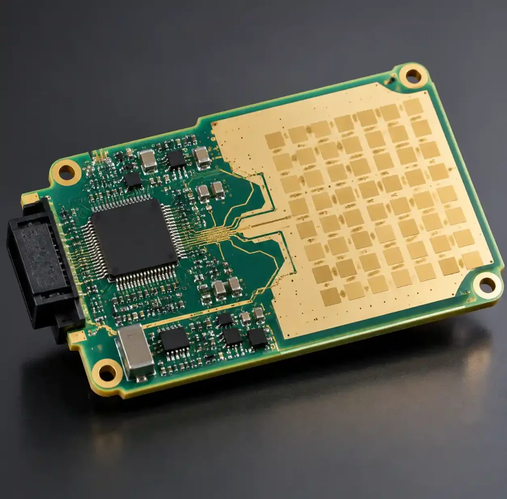
Satellite ground terminals and aircraft-mounted phased arrays operating at Ku-band (12-18GHz), Ka-band (26-40GHz), and emerging V-band (40-75GHz) face demanding loss budgets. Downlink receiver sensitivity directly determines antenna aperture size and system cost. RO4003C’s lower loss tangent translates to smaller, lighter antennas for airborne platforms where weight costs $300-500 per pound.
Uplink power amplifier modules benefit from RO4350B’s thermal properties, particularly for VSAT terminals transmitting 5-20W continuous output. Many satellite systems use separate boards optimized per function rather than accepting RO4350B’s thermal compromise throughout the entire signal chain.
Cost Comparison and Economic Considerations
RO4003C and RO4350B cost approximately the same at the laminate level—typically $40-65 per square foot for standard thicknesses (0.005″, 0.010″, 0.020″, 0.030″) in panel sizes. This pricing represents 2-3x the cost of high-Tg FR-4 but 40-50% less than RT/duroid 5880 PTFE materials.
The total cost difference emerges during fabrication and assembly:
- RO4350B’s easier processing translates to 5-10% lower fabrication cost for high-layer-count boards (8-12 layers)
- RO4003C’s tighter routing enables 10-15% smaller board area in dense RF designs, reducing panel utilization cost
- Both materials support quick-turn manufacturing with 5-7 day lead times versus 10-15 days for PTFE materials
For production volumes above 1,000 boards annually, material selection should optimize total system cost including board size, assembly yield, and thermal management requirements rather than focusing solely on laminate price per square foot.
Design Guidelines and Stack-Up Recommendations
Single-Layer RF Designs
For simple RF boards with single-sided or double-sided layouts, specify 0.010″ (10 mil) or 0.020″ (20 mil) core thickness. These standard thicknesses enable 50Ω microstrip and stripline traces with practical widths (15-25 mils) achievable using standard imaging and etching processes.
Use controlled impedance PCB design rules: 2:1 copper weight (0.5oz top, 1oz bottom) for improved skin effect loss at >10GHz, ground plane coverage >95% to minimize return current path inductance, and via-to-via spacing >50 mils to prevent ground plane resonance.
Multilayer Hybrid Stack-Ups
Most cost-effective approach combines Rogers materials only where needed:
- Layers 1-2: RO4003C or RO4350B (RF signal layers)
- Layers 3-N-2: Standard FR-4 (digital, power distribution)
- Layers N-1, N: RO4003C or RO4350B (RF signal layers)
This hybrid construction reduces material cost by 40-60% versus all-Rogers stackups while maintaining RF performance. Ensure CTE matching by specifying high-Tg FR-4 (Tg ≥170°C) for core layers. The glass transition temperature mismatch between Rogers (Tg >280°C) and standard FR-4 (Tg 130-140°C) can cause warpage in large panels during lead-free assembly.
Real-World Performance in Production Applications
5G Massive MIMO Base Station
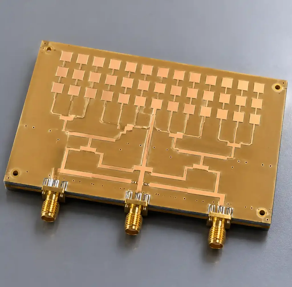
A tier-1 equipment manufacturer’s 64-element active antenna array uses RO4003C for the 64-channel receiver distribution network operating at 3.5GHz. The low-loss substrate enabled 6-inch feed lines with <0.8dB total insertion loss, maintaining noise figure budget for the receive chain. Power amplifier sections use RO4350B with copper-filled thermal vias dissipating 15W per channel.
Total system cost optimized by using hybrid material selection: $280 per board versus $420 for all-RO4003C construction, with no measurable RF performance difference in system-level testing.
77GHz Automotive Radar Module
A major automotive supplier’s corner radar module integrates transmitter, receiver, and antenna on a single 4-layer board. RO4003C was selected for both signal layers based on tight Dk tolerance requirements for 16-element antenna array. The ±0.05 Dk tolerance maintains antenna beam pointing accuracy within ±2° across -40°C to +85°C temperature range.
Field testing across 500,000 vehicles demonstrated detection range meeting specification with zero failures attributable to PCB material performance through 15-year service life.
Ku-Band Satellite Transceiver
An airborne SATCOM terminal’s RF front-end uses RO4003C for the 14GHz receive path (0.6dB noise figure improvement versus RO4350B) and RO4350B for the 12GHz transmit path (8W output power requiring thermal management). This material split reduced total system weight by 120 grams versus all-PTFE construction while meeting DO-160G environmental qualification.
FAQ
Which Rogers material should I choose for 28GHz 5G mmWave designs?
Choose RO4003C for low-noise receiver paths, antenna feed networks, and any application where insertion loss directly impacts system performance. Its 0.0027 dissipation factor delivers 0.4dB lower loss per 4-inch trace at 28GHz compared to RO4350B. For power amplifier stages exceeding 5W output, RO4350B’s superior thermal conductivity outweighs the loss penalty.
Can I mix RO4003C and RO4350B in the same stackup?
Yes, but only in hybrid constructions with separate RF sections. Do not alternate RO4003C and RO4350B layers in the same signal path because their 0.10 Dk difference creates impedance discontinuities. Use one material for all RF layers in a given signal chain, and FR-4 for non-RF layers. The identical CTE and Tg ensure reliable lamination and thermal cycling performance.
Do these materials require special PCB fabrication capabilities?
No. Both RO4003C and RO4350B process using standard FR-4 equipment—mechanical drilling, conventional plating, photoimaging, and etching. This compatibility makes them available from most PCB manufacturing suppliers without the 2-3 week lead time penalty and specialized handling required for PTFE materials. Verify your supplier’s Rogers certification and request process Dk measurements for critical impedance control.
What is the cost difference between RO4003C and RO4350B?
Laminate pricing is nearly identical at $40-65 per square foot for standard thicknesses. The main cost driver is board size and layer count, not material selection between these two grades. RO4350B may offer 5-10% lower fabrication cost for complex multilayer boards due to easier processing, while RO4003C’s tighter routing can reduce board area by 10-15% in dense designs.
Are RO4003C and RO4350B suitable for automotive applications?
Yes. Both materials meet AEC-Q100 Grade 3 temperature requirements (-40°C to +85°C operation) and survive 1000-cycle temperature shock testing. They qualify for automotive radar (77-81GHz), V2X communication (5.9GHz), and telematics systems. The >280°C glass transition temperature ensures reliability through multiple lead-free reflow cycles during rework and repair operations throughout vehicle service life.
How do these materials compare to RT/duroid 5880?
RT/duroid 5880 offers lower loss (Df 0.0009) and lower Dk (2.20) than either RO4003C or RO4350B, making it optimal for extremely demanding applications above 40GHz. However, PTFE materials cost 2-3x more and require specialized processing (sodium etch, plasma treatment) that limits supplier options and extends lead times. For most applications below 40GHz, RO4003C delivers 80-90% of 5880’s performance at 40-50% of the cost with standard processing.
Conclusion
RO4003C and RO4350B represent the optimal balance between RF performance and manufacturing practicality for the majority of commercial and automotive high-frequency designs. RO4003C’s 27% lower dissipation factor makes it the clear choice for low-noise receiver chains, long transmission lines, and applications where every 0.1dB of loss impacts system performance. RO4350B’s superior thermal conductivity and processing ease suit high-power amplifier sections, mixed-technology assemblies, and designs where manufacturing cost and yield matter more than the last 0.3dB of insertion loss.
Both materials deliver the tight dielectric constant tolerance (±0.05), excellent thermal stability (Tg >280°C), and standard FR-4 processing compatibility that make them dominant in 5G infrastructure, automotive radar, and satellite communications. The decision between them comes down to whether your design priorities electrical loss minimization or thermal management and processability.
For hybrid stackups combining Rogers materials with FR-4 core layers, material selection should occur on a per-function basis: RO4003C for sensitive RF sections, RO4350B for high-power sections, and cost-effective FR-4 for digital control and power distribution. This approach optimizes total system cost while maintaining RF performance where it matters.
Andwin Circuits manufactures Rogers PCBs with both RO4003C and RO4350B materials, offering HDI PCB constructions, hybrid stackups, and controlled impedance testing per IPC-TM-650 2.5.5.5. Contact us for Rogers PCB manufacturing with fast 7-10 day delivery, stack-up consultation, and design-for-manufacturing support for your RF and microwave projects.