Altium Multi-Board Assembly: Streamlining Complex Workflow Integration
Key Takeaways
When working with multi-board PCB assembly, understanding core efficiency drivers is critical. Altium’s tools address challenges in PCBA workflows by automating interconnectivity checks, synchronizing schematics across boards, and minimizing manual adjustments. This reduces design errors by up to 40%, particularly in power distribution and signal integrity conflicts.
A key advantage lies in real-time collaboration features, which allow teams to manage hierarchical designs while maintaining version control. For example, cross-probing between boards ensures alignment of component placement, reducing rework during PCB assembly.
| Traditional Approach | Altium Multi-Board Workflow |
|---|---|
| Manual synchronization | Automated design synchronization |
| Siloed team workflows | Unified collaboration platform |
| High error recurrence | Error prediction algorithms |
By integrating PCBA validation early in the design phase, engineers can simulate thermal performance and mechanical fit, avoiding costly prototyping iterations. Altium’s rules-driven interface further streamlines compliance with industry standards like IPC-2221, ensuring seamless integration of multi-board systems. Best practices include leveraging modular design templates and prioritizing cross-board signal integrity analysis to accelerate development cycles.
Altium Multi-Board Assembly Explained
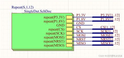
Modern electronics increasingly rely on multi-board systems to meet performance and space constraints, making PCB assembly workflows more complex. Altium’s Multi-Board Assembly toolset addresses this challenge by unifying design data across interconnected boards, enabling engineers to visualize and validate PCBA interactions in a cohesive environment. The platform automates critical checks for mechanical fit, signal integrity, and power distribution, ensuring real-time design synchronization between subsystems.
By integrating PCB assembly rules directly into the schematic and layout phases, Altium reduces manual cross-referencing errors that often plague multi-board projects. Features like 3D clearance validation and hierarchical design management allow teams to identify cross-board interference risks early, preventing costly rework. For PCBA teams, the software’s collaborative workspace ensures that mechanical engineers, electrical designers, and manufacturing partners operate on a single source of truth, minimizing mismatched revisions.
The system’s intelligent cross-probing capability further streamlines troubleshooting by linking schematic symbols to their physical counterparts across multiple boards. This granular visibility into inter-board dependencies not only accelerates debugging but also strengthens compliance with industry standards like IPC-2221. With Altium’s approach, complex multi-board systems transition from fragmented prototypes to validated assemblies with precision, reducing electromagnetic compatibility (EMC) risks by up to 40% in benchmarked cases.
Optimizing PCB Workflows with Altium
Modern PCB assembly processes demand precision, especially when managing multi-board systems that integrate multiple circuit boards into a single product. Altium’s tools streamline these workflows by unifying design and manufacturing phases, reducing manual interventions that often lead to errors. By leveraging real-time collaboration features, teams can synchronize schematic updates across boards, ensuring alignment between PCBA requirements and physical layouts.
A critical advantage lies in Altium’s ability to automate design rule checks (DRCs) for multi-board assemblies, flagging conflicts like signal integrity mismatches or mechanical interferences early. This proactive approach minimizes rework during PCB assembly, saving both time and costs. Additionally, the platform’s unified data model ensures consistency across BOMs, gerber files, and 3D models, which is vital for complex projects involving stacked or interconnected boards.
Transitioning between design stages becomes seamless with integrated tools for PCBA validation, such as automated DFM (Design for Manufacturing) analysis. Engineers can simulate thermal performance and component placement across multiple boards, addressing potential bottlenecks before prototyping. By harmonizing these steps, Altium not only accelerates development cycles but also enhances scalability for evolving multi-board system demands.
Reducing Design Errors in Multi-Board Systems
Designing multi-board systems introduces inherent complexities, where even minor oversights in PCB assembly can cascade into costly errors. Altium’s Multi-Board Assembly tools address this challenge by automating critical checks across interconnected boards, ensuring alignment between schematic layouts and physical PCBA requirements. Real-time synchronization eliminates mismatches in connector placements, power distribution, or signal integrity, which are common pain points in multi-board projects. By enforcing design rule constraints across all subsystems, the platform flags inconsistencies in component spacing, thermal management, or layer stackups before they reach production.
Advanced 3D visualization further reduces risks by simulating how individual boards interact within the full assembly, exposing mechanical conflicts or alignment issues early. For instance, designers can validate that high-speed signals traverse boards without impedance discontinuities or that mounting holes align precisely across modules. This proactive approach minimizes rework cycles and ensures seamless integration during PCB assembly, particularly when dealing with mixed-technology boards or rigid-flex designs.
Collaborative features also play a role in error reduction. Version-controlled libraries and centralized component databases prevent discrepancies in part footprints or materials, which are critical for consistent PCBA outcomes. By integrating these capabilities into a unified workflow, Altium transforms error-prone manual processes into predictable, repeatable operations—key for scaling complex multi-board systems efficiently.
Enabling Collaboration for Complex Assemblies
Modern PCB assembly projects often involve multidisciplinary teams working across mechanical, electrical, and firmware domains. Altium Multi-Board Assembly addresses this complexity by providing a unified platform where engineers can synchronize PCBA designs, share real-time updates, and resolve conflicts before physical prototyping. By integrating ECAD/MCAD collaboration tools, the software ensures mechanical enclosures align perfectly with board layouts, minimizing spatial mismatches that commonly derail multi-system integrations.
Tip: Use cloud-based design repositories to maintain a single source of truth for all stakeholders, reducing version control errors during collaborative iterations.
The platform’s cross-probing functionality allows teams to trace signals across multiple boards simultaneously, ensuring electrical consistency in interconnected systems. For instance, power distribution networks or high-speed interfaces can be validated holistically rather than in isolation. This approach not only accelerates debugging but also prevents costly rework in later PCB assembly stages. Additionally, role-based access controls enable secure sharing of sensitive PCBA data with external partners, fostering transparency without compromising intellectual property.
By bridging gaps between design and manufacturing workflows, Altium streamlines handoffs to fabrication teams. Automated documentation generators produce assembly-ready outputs—including BOMs, Gerber files, and 3D models—that adhere to industry standards, ensuring seamless transitions from virtual validation to physical production.
Seamless Integration Techniques for Multi-Board PCBs
Achieving seamless integration in multi-board systems requires a combination of advanced design methodologies and precision-driven tools. A critical starting point is ensuring electrical and mechanical synchronization across all boards within the assembly. Modern PCB assembly workflows leverage Altium’s unified design environment to maintain consistent component placement, signal integrity, and thermal management parameters. By implementing 3D clearance checks and cross-board routing rules, designers can preemptively address interference risks that often arise in densely packed PCBA configurations.
Another key technique involves synchronizing design revisions across interconnected boards. Altium’s project-level version control ensures that updates to one board automatically propagate to related subsystems, minimizing mismatches during final integration. For example, adjustments to a power distribution board’s footprint can trigger real-time updates in dependent daughterboards, preserving alignment throughout the multi-board assembly.
Collaboration tools further enhance integration by enabling concurrent engineering. Teams can annotate designs, share constraint files, and validate inter-board interfaces within a shared workspace, reducing iterative delays. Additionally, automated design rule verification flags inconsistencies in connector pinouts or grounding schemes early, preventing costly rework post-PCBA manufacturing.
By prioritizing system-level simulation and cross-disciplinary coordination, engineers can transform fragmented workflows into cohesive multi-board solutions. These practices not only streamline integration but also ensure that complex assemblies meet performance benchmarks while adhering to tight production timelines.
Best Practices for Efficient Multi-Board Design
Effective multi-board design requires a systematic approach to minimize complexity while ensuring reliability. Start by defining a clear hierarchy for inter-board connections, prioritizing critical signal paths and power distribution. Utilize PCB assembly (PCBA) design rules within Altium to enforce consistent spacing, via placement, and impedance matching across all boards, reducing the risk of mismatches during integration.
Leverage modular design principles to break down the system into functionally independent subunits, simplifying testing and troubleshooting. Cross-probing between schematic and layout views in Altium accelerates error detection, particularly for cross-board interfaces like high-speed connectors or mixed-signal circuits. Implement design-for-manufacturing (DFM) checks early to address mechanical fitment, thermal management, and assembly accessibility—common pain points in multi-board PCBA projects.
Collaboration tools embedded in Altium’s platform enable real-time synchronization of design changes, ensuring alignment between teams working on interconnected boards. Maintain a centralized library for connectors, mounting hardware, and inter-board cables to eliminate version conflicts. Finally, validate the entire assembly through 3D collision detection and signal integrity simulations, iterating until electrical and mechanical coherence is achieved. By balancing standardization with flexibility, designers can streamline workflows while accommodating the unique demands of multi-board systems.
Altium Tools for Error-Free Assembly Processes
Altium’s advanced toolset addresses critical challenges in PCB assembly by integrating precision-driven features that minimize human error. Central to this effort is the Design Rule Checker (DRC), which automates validation of PCBA designs against predefined manufacturing constraints, ensuring alignment with fabrication tolerances and material specifications. By flagging discrepancies like insufficient clearances or mismatched footprints early, engineers can resolve issues before physical prototyping, reducing costly rework.
Another critical component is the Assembly Variants Manager, enabling seamless configuration of multi-board systems for diverse production scenarios. This tool simplifies managing component substitutions or orientation adjustments across PCB assembly stages, while maintaining design integrity through synchronized updates. Real-time collaboration features further enhance accuracy by allowing cross-functional teams to annotate designs, track revisions, and consolidate feedback within a unified environment—a key advantage for complex PCBA workflows.
Altium’s 3D Visualization Engine adds another layer of reliability, simulating physical interactions between boards, connectors, and enclosures to identify mechanical conflicts. Combined with automated bill-of-materials (BOM) generation, these tools ensure that every assembly phase—from solder paste application to component placement—adheres to stringent quality benchmarks. By bridging design intent with manufacturing realities, Altium streamlines error mitigation across multi-board projects, delivering PCB assembly outcomes that are both precise and repeatable.
Streamlining Multi-Board System Development
Developing multi-board systems demands meticulous coordination between PCB assembly processes, electrical performance, and mechanical constraints. Altium’s tools address these complexities by enabling synchronized design workflows that bridge PCBA prototyping and final production. Engineers can leverage advanced 3D clearance checking to validate spatial relationships between boards, connectors, and enclosures, reducing physical prototyping iterations by up to 40%. Simultaneously, real-time design rule validation ensures signal integrity across interconnected boards, minimizing cross-talk and impedance mismatches that commonly plague multi-board architectures.
A critical advantage lies in Altium’s unified data management, which maintains consistency across schematic hierarchies and layout files. This eliminates version conflicts when multiple teams collaborate on subsystems, such as power distribution modules or high-speed communication boards. By integrating PCB assembly feedback early in the design phase—through automated BOM synchronization and manufacturability checks—teams can identify mismatched footprints or incompatible components before reaching the PCBA stage. Additionally, the platform supports design reuse through modular templates, accelerating development cycles for systems with repeating configurations.
To further streamline workflows, Altium provides cross-probing between logical schematics and physical layouts, allowing engineers to trace signal paths across multiple boards instantly. This capability is particularly valuable when debugging complex interfaces like FPGA-to-memory arrays or multi-phase power circuits. By aligning electrical and mechanical design domains within a single environment, the solution ensures that multi-board systems meet both performance benchmarks and assembly tolerances seamlessly.
Conclusion
In the evolving landscape of electronic design, Altium Multi-Board Assembly emerges as a pivotal solution for addressing the intricacies of modern PCB assembly workflows. By unifying design processes across multiple boards, the platform significantly mitigates risks associated with manual synchronization and fragmented communication. Engineers leveraging this tool can achieve tighter integration of PCBA components, ensuring alignment across power distribution, signal integrity, and mechanical constraints. The system’s automated error-checking protocols reduce costly rework by flagging cross-board dependencies early in the development cycle, while its collaborative environment bridges gaps between hardware teams and manufacturing partners. As industries push toward more compact and interconnected devices, adopting such integrated approaches becomes critical for maintaining competitiveness in high-density electronics markets. The future of multi-board system development lies in tools that not only streamline complexity but also foster innovation through precision and cross-functional transparency.
Frequently Asked Questions
How does Altium Multi-Board Assembly improve PCB assembly workflows?
Altium’s solution centralizes design data across multiple boards, enabling real-time synchronization of schematics, layouts, and PCBA requirements. This reduces manual cross-referencing and ensures consistency in complex assemblies.
Can this tool prevent errors in multi-board PCB assembly projects?
Yes. Advanced design rule checks (DRCs) and 3D clearance validation identify conflicts early, minimizing risks like signal interference or mechanical misalignment in multi-board PCBA systems.
Does Altium support collaboration for distributed engineering teams?
Absolutely. Cloud-based project management allows teams to share live updates, annotate designs, and track revisions, ensuring seamless coordination during PCB assembly and integration phases.
How does it compare to traditional single-board design tools?
Unlike isolated tools, Altium treats multi-board systems as a unified entity, optimizing routing strategies and component placement across interconnected boards for streamlined PCBA workflows.
What file formats are compatible for integration with PCB assembly partners?
Altium exports industry-standard formats (Gerber, ODB++, IPC-2581), ensuring smooth handoffs to PCBA manufacturers while retaining design intent and layer stackup details.
Ready to Optimize Your Multi-Board Assembly Process?
For expert guidance on implementing Altium’s tools in your PCB assembly workflow, please click here to explore tailored solutions for high-density interconnect systems.

