Automated Soldering Methods for PCB Boards: A Comprehensive Guide
Introduction to PCB Automated Soldering
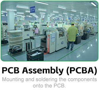
Printed Circuit Board (PCB) soldering has evolved significantly from manual hand-soldering techniques to sophisticated automated processes that ensure precision, consistency, and high throughput in electronics manufacturing. Automated soldering machines have become indispensable in modern electronics production, offering numerous advantages over manual methods, including improved quality control, reduced human error, and increased production speed.
This article explores the various automated soldering methods used in PCB assembly, their working principles, advantages, limitations, and appropriate applications. As electronic devices continue to become smaller and more complex, understanding these automated soldering techniques becomes increasingly important for manufacturers aiming to maintain competitiveness in the electronics industry.
Wave Soldering
Principle and Process
Wave soldering represents one of the earliest and most widely used automated soldering techniques for PCB assembly. This method is particularly effective for through-hole components and has been adapted for certain surface-mount applications as well.
The wave soldering process begins with the application of flux to the underside of the PCB, typically through spraying or foaming methods. The board then passes over a preheating stage that activates the flux and gradually raises the board’s temperature to prevent thermal shock. The critical stage follows as the PCB contacts a molten solder wave – a standing wave of liquid solder maintained at approximately 250°C (for lead-free solders). This wave creates the electrical and mechanical connections between component leads and PCB pads.
Equipment Configuration
Modern wave soldering machines consist of several key components:
- Flux application unit: Precisely applies flux to the board surfaces
- Preheat zone: Typically uses infrared heaters or convection systems
- Solder pot: Contains molten solder (usually SAC alloys for lead-free processes)
- Pump and nozzle system: Generates the laminar solder wave
- Cooling zone: Allows joints to solidify properly before handling
Advantages and Limitations
Wave soldering offers several benefits:
- High throughput capability (up to 20,000 boards per day)
- Excellent for through-hole components
- Relatively low operational costs for high-volume production
- Proven, reliable technology with well-understood parameters
However, limitations include:
- Not suitable for fine-pitch surface-mount devices (SMDs)
- Higher solder consumption compared to other methods
- Potential for bridging on dense boards
- Thermal stress on sensitive components
Recent Advancements
Modern wave soldering systems have incorporated several improvements:
- Dual wave systems: Combining turbulent and laminar waves to reduce defects
- Nitrogen inerting: Minimizing oxidation for improved joint quality
- Selective wave nozzles: Targeting solder application to specific areas
- Advanced flux management systems: Precise control of flux application
Reflow Soldering
Fundamentals of Reflow Technology
Reflow soldering has become the dominant method for surface-mount technology (SMT) assembly, offering precise control for modern high-density PCB designs. Unlike wave soldering, reflow processes apply solder before component placement, typically in the form of solder paste.
The reflow process involves four main stages:
- Preheat: Gradual temperature increase to activate flux and prevent thermal shock
- Soak: Allows temperature equalization across the PCB
- Reflow: Temperature exceeds solder melting point, forming metallurgical bonds
- Cooling: Controlled solidification of solder joints
Reflow Oven Types
Several reflow oven technologies exist, each with distinct characteristics:
- Convection Reflow:
- Most common type in modern manufacturing
- Uses heated nitrogen or air circulated by fans
- Excellent temperature uniformity
- Suitable for lead-free processes requiring higher temperatures
- Vapor Phase Reflow:
- Utilizes heat transfer fluids with specific boiling points
- Extremely uniform heating
- Lower oxygen environment reduces oxidation
- Higher equipment and operational costs
- Infrared Reflow:
- Uses IR radiation for heating
- Faster thermal response
- Potential for uneven heating due to component shadowing
- Less common in modern production
- Laser Reflow:
- Highly localized soldering with laser energy
- Minimal thermal stress on components
- Very low throughput, typically for rework or specialty applications
Solder Paste Considerations
The quality of reflow soldering heavily depends on proper solder paste application:
- Composition: Solder powder (typically SAC305 for lead-free) suspended in flux
- Particle size: Ranges from Type 3 (25-45μm) to Type 6 (5-15μm) for fine-pitch
- Rheology: Affects printing performance and slump characteristics
- Stencil design: Critical for precise paste deposition
Process Control Parameters
Key parameters that require careful control in reflow soldering:
- Temperature profile: Must match solder paste specifications
- Time above liquidus (TAL): Typically 30-90 seconds
- Peak temperature: Usually 20-40°C above solder melting point
- Ramp rates: Typically 1-3°C/second to prevent defects
Selective Soldering
Concept and Applications
Selective soldering bridges the gap between wave and reflow technologies, offering precision soldering for specific board areas. This method proves particularly valuable for:
- Mixed-technology boards (combining SMT and through-hole)
- Heat-sensitive components that cannot withstand wave soldering
- High-reliability applications requiring precise solder control
- Boards with limited soldering areas due to shielding or mechanical constraints
Machine Configurations
Selective soldering systems come in several configurations:
- Robotic Selective Soldering:
- Programmable soldering head moves to target locations
- Can handle complex board geometries
- Relatively slow compared to wave soldering
- Drag Soldering:
- PCB moves over a stationary solder nozzle
- Good for linear connector arrays
- Faster than robotic systems for certain patterns
- Dip Soldering:
- Components are dipped into a small solder pot
- Useful for through-hole connectors
- Limited to accessible board areas
Process Characteristics
Selective soldering typically involves:
- Localized flux application (spray or drop dispensing)
- Precise thermal management (preheat may be localized)
- Controlled solder delivery (miniature waves or fountains)
- Often uses nitrogen atmosphere for improved quality
Advantages Over Other Methods
Key benefits of selective soldering include:
- Reduced thermal stress on sensitive components
- Lower solder consumption compared to wave soldering
- Ability to solder areas inaccessible to wave machines
- Flexibility to handle diverse product mixes
- Improved joint quality through precise parameter control
Laser Soldering
Technology Overview
Laser soldering represents the pinnacle of precision in automated soldering, using focused laser energy to create solder joints with minimal heat affected zones. This method finds particular use in:
- High-value electronics (medical, aerospace, military)
- Microelectronics and miniaturized components
- Rework and repair operations
- Heat-sensitive assemblies
System Components
A typical laser soldering system includes:
- Laser source: Usually diode (808-980nm) or fiber lasers
- Beam delivery optics: For precise energy focusing
- Vision system: For component recognition and alignment
- Solder feeding mechanism: Wire or preforms
- Temperature monitoring: Often with pyrometers or IR cameras
Process Characteristics
Laser soldering offers unique advantages:
- Localized heating: Only the joint area reaches high temperature
- Precise energy control: Can adjust power in real-time
- No physical contact: Eliminates mechanical stress
- Flexible access: Can reach confined areas
- Clean process: Minimal flux requirements
Limitations and Challenges
Despite its advantages, laser soldering faces several challenges:
- High equipment costs
- Slow processing speed compared to mass soldering
- Requires precise joint accessibility
- Demanding programming for complex boards
- Limited to certain joint geometries
Emerging Trends in Automated Soldering
Industry 4.0 Integration
Modern automated soldering systems increasingly incorporate smart manufacturing concepts:
- IoT connectivity: Real-time monitoring and data collection
- Machine learning: Adaptive process optimization
- Predictive maintenance: Reducing unplanned downtime
- Digital twins: Virtual process simulation and testing
Advanced Materials
New material developments impact soldering processes:
- Low-temperature solders: Reducing thermal stress
- High-reliability alloys: For automotive and aerospace
- Novel flux chemistries: Halogen-free and low-residue formulations
- Conductive adhesives: Alternative joining methods
Miniaturization Challenges
As components continue shrinking, soldering faces new hurdles:
- 01005 and smaller components: Require ultra-fine solder deposition
- 3D packaging: Demanding new soldering approaches
- Heterogeneous integration: Mixing different technologies on single substrates
Environmental Considerations
Sustainability concerns drive process innovations:
- Lead-free soldering: Continued development of reliable alloys
- Energy efficiency: Reducing power consumption in soldering equipment
- Waste reduction: Solder dross minimization and recycling
- Cleaner processes: Reducing VOC emissions and hazardous materials
Conclusion
Automated soldering methods for PCB assembly have evolved into sophisticated, highly controlled processes that meet the demanding requirements of modern electronics manufacturing. From the high-throughput capabilities of wave soldering to the precision of laser soldering, each method offers unique advantages suited to specific applications and product requirements.
As electronic devices continue advancing, soldering technologies must correspondingly evolve to address challenges of miniaturization, mixed-technology assemblies, and higher reliability demands. The integration of smart manufacturing technologies with traditional soldering processes promises to further enhance quality, efficiency, and flexibility in PCB assembly operations.
Manufacturers must carefully evaluate their product mix, volume requirements, quality standards, and cost targets when selecting the appropriate automated soldering method. Understanding the capabilities and limitations of each technology enables optimal process selection and implementation, ensuring competitive advantage in the fast-paced electronics industry.

