Capacitive Touch Flex PCB: Design, Applications, and Future Trends
Abstract
Capacitive touch technology has revolutionized human-machine interfaces (HMI) across various industries, from consumer electronics to automotive systems. Flexible printed circuit boards (Flex PCBs) have further enhanced this technology by enabling innovative form factors and reliable performance in constrained spaces. This article explores the design principles, materials, manufacturing processes, applications, and future trends of capacitive touch Flex PCBs, providing a comprehensive overview of this advanced technology.
1. Introduction
Capacitive touch sensing is a widely adopted technology that detects touch input based on changes in capacitance caused by a conductive object (such as a human finger). Unlike resistive touchscreens, capacitive touch offers higher sensitivity, multi-touch support, and better durability.
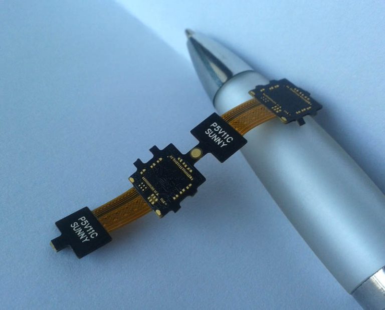
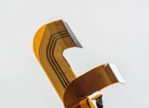
Flex PCBs, made from flexible polymer substrates like polyimide, allow for bending and folding, making them ideal for compact and complex device designs. Combining capacitive touch sensing with Flex PCBs enables lightweight, durable, and space-efficient touch interfaces in modern electronics.
2. Fundamentals of Capacitive Touch Technology
2.1 Capacitive Sensing Principles
Capacitive touch sensors work by detecting changes in capacitance when a conductive object (e.g., a finger) approaches or touches the sensor. There are two primary types:
- Surface Capacitive Touch: Uses a uniform conductive layer (e.g., ITO) with electrodes at the corners. A touch distorts the electrostatic field, and the controller calculates the touch position.
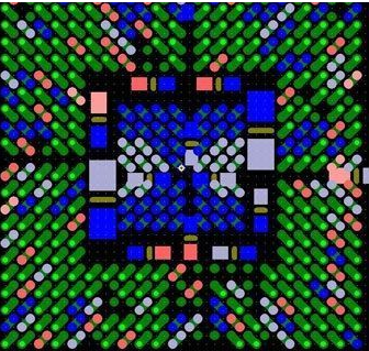
- Projected Capacitive Touch (PCT): Uses a grid of electrodes (TX and RX lines) to enable multi-touch functionality. PCT is more common in modern devices due to its higher accuracy and scalability.
2.2 Advantages of Capacitive Touch
- High sensitivity and responsiveness
- Multi-touch support
- Durability (no moving parts)
- Better optical clarity compared to resistive touch
3. Flex PCB Technology for Capacitive Touch
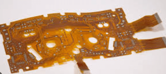
3.1 Structure of Capacitive Touch Flex PCBs
A typical capacitive touch Flex PCB consists of:
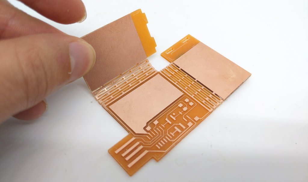
- Substrate: Polyimide (PI) is the most common due to its flexibility, thermal stability, and electrical insulation.
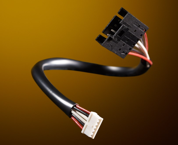
- Conductive Traces: Usually made of copper, with possible plating (e.g., gold or silver) for better conductivity.
- Dielectric Layers: Insulating materials to prevent short circuits.
- Protective Coatings: Coverlays (polyimide with adhesive) or solder mask to shield the circuitry.
- Transparent Conductive Materials (for displays): Indium Tin Oxide (ITO) or alternative materials like silver nanowires or conductive polymers.
3.2 Key Design Considerations
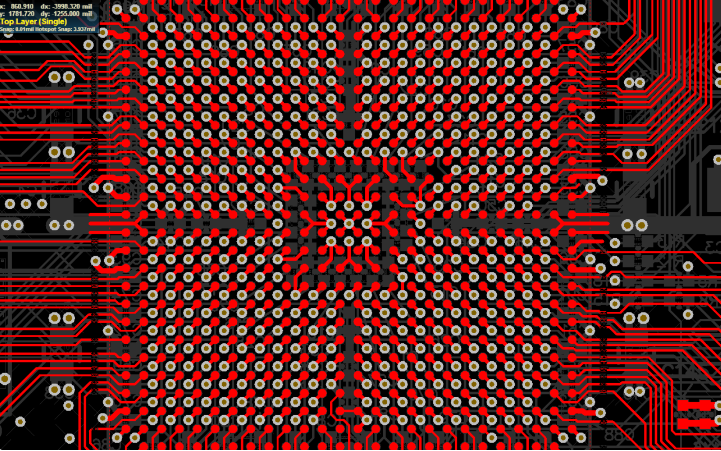
- Trace Routing: Minimize cross-talk by proper spacing and shielding.
- Bend Radius: Ensure traces can withstand repeated bending without cracking.
- Signal Integrity: Impedance control is critical for high-frequency touch signals.
- Grounding: Proper grounding reduces noise and improves touch accuracy.
4. Manufacturing Process
4.1 Material Selection
- Substrate: Polyimide (PI) or PET (for lower-cost applications).
- Conductive Layers: Rolled annealed (RA) copper or electro-deposited (ED) copper.
- Adhesives: Acrylic or epoxy-based for layer bonding.
4.2 Fabrication Steps
- Patterning: Photolithography or laser etching to create circuit traces.
- Etching: Chemical etching to remove excess copper.
- Lamination: Applying coverlays or additional layers.
- Plating: Optional ENIG (Electroless Nickel Immersion Gold) or HASL (Hot Air Solder Leveling) for better conductivity.
- Cutting: Laser or die-cutting to final shape.
- Testing: Electrical and functional testing to ensure touch sensitivity.
5. Applications of Capacitive Touch Flex PCBs
5.1 Consumer Electronics
- Smartphones & Tablets: Flex PCBs enable edge-to-edge touchscreens and foldable displays.
- Wearables: Smartwatches and fitness bands use flexible touch sensors for curved interfaces.
5.2 Automotive
- Touchscreen Dashboards: Flex PCBs withstand vibrations and temperature variations.
- Steering Wheel Controls: Capacitive buttons replace mechanical switches for a sleek design.
5.3 Medical Devices
- Portable Diagnostic Equipment: Flexible touch interfaces enhance usability in handheld medical tools.
5.4 Industrial HMIs
- Rugged Touch Panels: Flex PCBs with protective coatings resist harsh environments.
6. Challenges and Solutions
6.1 Signal Noise
- Shielding: Adding ground planes or mesh layers reduces EMI.
- Filtering Algorithms: Advanced touch controllers filter out environmental noise.
6.2 Durability in Dynamic Flexing
- Reinforced Traces: Using thicker copper or additional PI layers improves longevity.
- Strain Relief: Designing bend areas with gradual curves minimizes stress.
6.3 Cost Considerations
- Alternative Materials: Using silver ink or conductive polymers instead of ITO can reduce costs.
- Optimized Designs: Reducing layer count and complexity lowers manufacturing expenses.
7. Future Trends
7.1 Advanced Materials
- Graphene & Carbon Nanotubes: Emerging materials for highly flexible and transparent electrodes.
- Stretchable Electronics: Research is ongoing for fully stretchable touch sensors.
7.2 Integration with Other Technologies
- Force Touch: Combining capacitive touch with pressure sensing for richer input methods.
- Haptic Feedback: Embedded actuators in Flex PCBs provide tactile responses.
7.3 Sustainability
- Biodegradable Substrates: Development of eco-friendly Flex PCB materials.
- Recycling Methods: Improved processes for recovering precious metals from discarded PCBs.
8. Conclusion
Capacitive touch Flex PCBs represent a powerful synergy between touch sensing and flexible electronics, enabling innovative designs across industries. As materials and manufacturing techniques evolve, these PCBs will continue to drive advancements in wearable tech, automotive interfaces, and beyond. Engineers must balance performance, durability, and cost to fully leverage this technology’s potential.