Cause of PCB Inner Layer Shorts
1.Impact of Raw materials on inner layer Shorts:
The dimensional stability of multilayer PCB materials is the primary factor affecting the positioning accuracy of inner layers.The thermal expansion coefficients of the substrate and copper foil must also be considered.Regarding the physical properties of the substrate used,laminates all contain ploymers,which undergo a structual changes at a certain temperature,conmonly known as the glass transition temperature is a unique property of most polymers,second only to the coefficient of thermal expansion,and is the most important characteristic of laminates.A comparison of two commonly used materials show that the glass transition temperature of epoxy glass cloth laminates and polyimide are 120°C and 230°C, respectively. Below 150°C, the natural thermal expansion of epoxy glass cloth laminates is approximately 0.01 in/in, while that of polyimide is only 0.001 in/in.
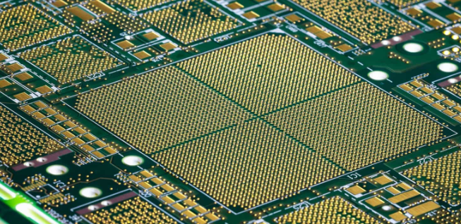
According to relevant technical data, the thermal expansion coefficient of a laminate in the X and Y directions ranges from 12-16 ppm/°C per 1°C increase, while the Z-direction thermal expansion coefficient is 100-200 ppm/°C, an order of magnitude greater than the X and Y directions.However, during testing, it was found that when the temperature exceeded 100°C, the Z-axis expansion between the laminate and the hole became inconsistent and the difference became larger. The plated through-hole has a lower natural expansion rate than the surrounding laminate. Since the laminate thermally expands faster than the hole, the through-hole is stretched in the direction of the laminate deformation. This stress condition generates tensile stress in the through-hole. As the temperature rises, this tensile stress continues to increase. When the stress exceeds the fracture strength of the through-hole plating, the plating will fracture. Furthermore, the laminate’s higher thermal expansion coefficient significantly increases stress on the inner layer conductors and pads, causing cracks between the conductors and pads and short circuits in the inner layers of multilayer PCBs. Therefore, when manufacturing PCBs suitable for high-density packaging structures like BGAs, the technical requirements for raw materials must be carefully analyzed. The thermal expansion coefficients of the base material and copper foil must be essentially matched.

2. The Impact of Positioning System Accuracy on Inner Layer Short Circuits
Positioning is essential during the substrate generation,circuit pattern products that require positioning can present a series of technical problem due to differences in positioning accuracy.Even the slightest mistake can lead to shorts circuits in the inner layers of multilayer PCBs.The choice of positioning method should be determined by the accuracy,suitablity,and effectiveness of the chosen positioning method.
3. The Impact of Inner Layer Etching Quality on Inner Layer Short Circuits
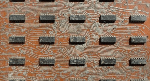
The inner layer etching process can easily produce residual copper spots.These spots are sometimes extremely small and difficult to detect visually without optical testing.These spots can be carried over to the lamination process,where they are pressed into the inner layers of the multilayer PCB.Due to the high density of the inner layers,this residual copper is most likely to overlap between two conductors,causing short circuit in the inner layers of the multilayer PCB.
4.The Impact of Lamination Process Parameters on Inner Layer Short Circuits
Inner layer boards must be positioned using dowel pins during lamination. If the pressure applied during assembly is uneven, the dowel holes in the inner layer boards will deform. Excessive pressing pressure will also generate significant shear and residual stresses, leading to layer shrinkage and deformation. These factors can all cause short circuits in the inner layers of multilayer PCBs, resulting in scrap.
5.The Impact of Drilling Quality on Inner Layer Short Circuits
Hole Position Error Analysis
To achieve high-quality and reliable electrical connections, the minimum gap between the pad and the conductor after drilling must be 50μm. Maintaining this small width requires extremely high drilling accuracy, with the resulting error within or equal to the dimensional tolerance requirements specified by the process. However, the hole position error in drilling small holes is primarily determined by the accuracy of the drilling machine, the geometry of the drill bit, the characteristics of the cover and backing plate, and the process parameters. Based on experience accumulated from actual production processes, four factors contribute to this problem: the amplitude of the drilling machine’s vibration relative to the actual hole position, spindle deflection, slippage at the drill bit’s entry point into the substrate, and bending deformation caused by resistance from the glass fiber and drill cuttings after entering the substrate. These factors can all contribute to internal hole position deviation, potentially leading to short circuits.
2.To address and eliminate the possibility of excessive hole position deviations, a step-by-step drilling process is recommended. This can significantly reduce chip removal and drill bit temperature rise. Therefore, drill bit geometry (cross-sectional area, drill core thickness, taper, flute angle, flute length-to-land ratio, etc.) should be modified to increase drill bit rigidity, significantly improving hole position accuracy. Furthermore, the proper selection of the cover plate and drilling process parameters are crucial to ensure that hole position accuracy remains within process specifications. In addition to the aforementioned guarantee conditions, external factors must also be considered. Improper positioning of the inner layer can lead to through-hole deviation during drilling, which can also cause internal layer short circuits or short circuits.