Causes and Solutions for PCB Overheating: A Comprehensive Guide
Introduction
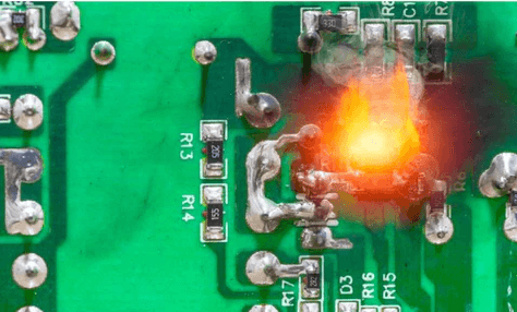
Printed Circuit Board (PCB) overheating is one of the most common and challenging issues faced by electronics designers and manufacturers. As electronic devices become more powerful and compact, thermal management has emerged as a critical factor in product reliability and longevity. This 2000-word article explores the root causes of PCB overheating and provides practical solutions to mitigate these thermal challenges.
Understanding PCB Overheating
PCB overheating occurs when components or traces on the board exceed their recommended operating temperatures. This can lead to various problems including:
- Reduced component lifespan
- Performance degradation
- Intermittent failures
- Complete system breakdown
- Safety hazards (in extreme cases)
The ideal operating temperature for most PCBs typically ranges between -40°C to 85°C, though specific limits depend on the components and materials used.
Primary Causes of PCB Overheating
1. Inadequate Power Distribution
Poor power distribution design is a leading cause of localized heating in PCBs. Issues include:
- Undersized power traces that can’t handle current loads
- Improper power plane design
- Insufficient via count for current transfer between layers
- Voltage regulator inefficiencies generating excess heat
2. Component Selection and Placement
- High-power components placed too close together create thermal hotspots
- Using components near their maximum ratings without proper derating
- Failure to consider component thermal resistance (Rθ) during selection
- Obstructed airflow around heat-generating components
3. Insufficient Thermal Management
- Lack of proper heat sinks or thermal vias
- Inadequate copper pour for heat dissipation
- Poor selection of PCB substrate material with low thermal conductivity
- Absence of cooling fans or other active cooling mechanisms
4. Environmental Factors
- Operation in high ambient temperatures
- Restricted airflow in enclosures
- Dust accumulation insulating components
- High humidity affecting thermal properties
5. Design Flaws
- Insufficient board space for proper heat dissipation
- Incorrect layer stackup for thermal management
- Lack of thermal relief in pads
- Poor solder joints increasing resistance
6. Manufacturing Defects
- Insufficient solder causing high-resistance connections
- Delamination affecting heat transfer
- Contamination altering thermal properties
- Improper curing of conformal coatings
Solutions to PCB Overheating Problems
1. Design-Level Solutions
Optimal Component Placement:
- Separate heat-generating components to prevent thermal coupling
- Position sensitive components away from heat sources
- Consider thermal profiles when planning component locations
Improved PCB Layout:
- Use appropriate trace widths for current carrying capacity
- Implement thermal relief patterns for components
- Increase copper weight in high-current areas
- Utilize thermal vias under heat-generating components
Power Distribution Optimization:
- Implement proper power plane design
- Use multiple vias for high-current connections
- Consider thicker copper layers for power applications
2. Material Selection
PCB Substrate:
- Choose materials with higher thermal conductivity (e.g., metal-core PCBs)
- Consider ceramic substrates for extreme conditions
- Use high-temperature laminates when needed
Thermal Interface Materials:
- Select appropriate thermal pads or pastes
- Implement thermally conductive adhesives where applicable
3. Active Cooling Solutions
Forced Air Cooling:
- Incorporate strategically placed cooling fans
- Design optimal airflow paths through the enclosure
- Consider blower-style fans for directional cooling
Liquid Cooling:
- Implement cold plates for high-power applications
- Consider microchannel cooling for compact designs
- Explore two-phase cooling systems for extreme cases
4. Passive Cooling Techniques
Heat Sinks:
- Select appropriate heat sink sizes and materials
- Implement board-mounted heat sinks
- Consider extruded or bonded-fin designs
Thermal Vias:
- Use arrays of thermal vias under hot components
- Optimize via diameter and plating thickness
- Fill vias with thermally conductive materials when needed
Copper Pour Techniques:
- Implement thermal relief copper pours
- Use hatched copper for large areas to prevent warping
- Connect copper areas to ground planes for better heat dissipation
5. Manufacturing Process Improvements
Soldering Process:
- Ensure proper solder joint formation
- Control reflow profiles to prevent thermal damage
- Implement solder thickness monitoring
Quality Control:
- Conduct thermal imaging during testing
- Implement automated optical inspection for solder defects
- Perform thermal cycling tests
6. System-Level Approaches
Thermal Simulation:
- Conduct thermal analysis during design phase
- Use computational fluid dynamics (CFD) for airflow optimization
- Perform finite element analysis for thermal stress
Power Management:
- Implement dynamic voltage and frequency scaling
- Consider power gating for unused circuits
- Use efficient voltage regulators with proper heat sinking
Environmental Controls:
- Design enclosures with proper ventilation
- Consider filtered air intakes in dusty environments
- Implement temperature monitoring and shutdown circuits
Advanced Thermal Management Techniques
1. Embedded Cooling Technologies
- Microfluidic cooling channels within PCBs
- Embedded heat pipes or vapor chambers
- Thermoelectric cooling modules
2. Phase Change Materials
- Implement materials that absorb heat during phase transition
- Use paraffin-based or salt hydrate PCMs
- Design for cyclic heating applications
3. 3D Printing Solutions
- Create custom heat sink geometries
- Print conformal cooling structures
- Manufacture complex thermal management components
Best Practices for PCB Thermal Management
- Early Consideration: Address thermal issues from the initial design phase
- Comprehensive Analysis: Combine electrical and thermal simulations
- Margin Design: Build in thermal safety margins for reliability
- Iterative Testing: Prototype and validate thermal performance
- Documentation: Maintain thorough thermal design records
Case Studies
Case 1: High-Power LED Driver Board
Problem: LED driver ICs overheating causing premature failure
Solution: Implemented thermal vias array, copper pour, and external heat sink
Result: Temperature reduced by 35°C, lifespan increased 5x
Case 2: Automotive Control Module
Problem: Thermal cycling causing solder joint failures
Solution: Switched to high-temperature laminate and improved component spacing
Result: Reliability improved to meet automotive standards
Case 3: Server Motherboard
Problem: VRM components overheating under load
Solution: Added liquid cold plate with microchannels
Result: Sustained operation at full load with 50% lower temperatures
Future Trends in PCB Thermal Management
- Nanomaterials: Graphene and carbon nanotube applications
- AI-Optimized Designs: Machine learning for thermal layout optimization
- Smart Cooling: Adaptive cooling systems with real-time monitoring
- Integrated Solutions: Combined electrical and thermal co-design tools
Conclusion
PCB overheating is a multifaceted challenge that requires a systematic approach from design through manufacturing and operation. By understanding the root causes and implementing appropriate solutions at each stage, engineers can create reliable, high-performance electronic products that meet thermal requirements. The key lies in early thermal consideration, proper material selection, optimized layout design, and appropriate cooling solutions tailored to the specific application.
As electronic devices continue to push performance boundaries while shrinking in size, innovative thermal management solutions will remain critical to product success. By applying the principles and techniques outlined in this article, designers can effectively address PCB overheating challenges and deliver robust, reliable electronic systems


