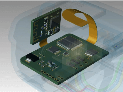
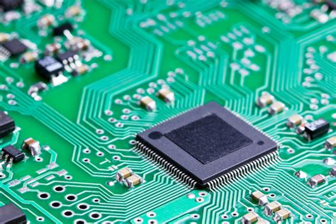
Ceramic resonator on pcb
Understanding The Role Of Ceramic Resonators In PCB Design
In the realm of printed circuit board (PCB) design, the selection of components plays a pivotal role in determining the overall performance and reliability of electronic devices. Among these components, ceramic resonators have emerged as a crucial element, particularly in applications requiring precise frequency control. Understanding the role of ceramic resonators in PCB design necessitates a comprehensive exploration of their functionality, advantages, and integration techniques.
Ceramic resonators are piezoelectric devices that generate oscillations at a specific frequency, serving as a frequency reference in electronic circuits.
Unlike quartz crystals, which are also used for frequency control, ceramic resonators offer a cost-effective alternative with certain trade-offs in terms of precision and stability. However, their compact size, robustness, and ease of integration make them an attractive choice for many applications, including microcontrollers, communication devices, and consumer electronics.
One of the primary advantages of ceramic resonators is their ability to provide a stable frequency output over a wide temperature range.
This characteristic is particularly beneficial in environments where temperature fluctuations are common, as it ensures consistent performance without the need for additional temperature compensation mechanisms. Furthermore, ceramic resonators exhibit low power consumption, which is a critical consideration in battery-powered devices where energy efficiency is paramount.
Incorporating ceramic resonators into PCB design requires careful consideration of several factors to optimize their performance.
Firstly, the placement of the resonator on the PCB is crucial. It is generally recommended to position the resonator as close as possible to the associated microcontroller or oscillator circuit to minimize parasitic inductance and capacitance, which can adversely affect the resonator’s frequency stability. Additionally, the layout should minimize the length of the traces connecting the resonator to the circuit, further reducing potential interference.
Moreover, the choice of resonator package and mounting style can significantly impact the overall design.
Surface-mount technology (SMT) packages are commonly used due to their small footprint and ease of assembly, which align with modern PCB manufacturing processes. However, through-hole packages may be preferred in applications where mechanical stability is a priority, as they offer enhanced resistance to physical stress and vibration.
Transitioning to the electrical characteristics, it is essential to match the resonator’s load capacitance with the circuit’s requirements to achieve the desired frequency accuracy.
This involves selecting appropriate load capacitors and ensuring that the PCB layout accommodates these components without introducing unwanted parasitic effects. Additionally, designers must consider the resonator’s drive level, as excessive drive can lead to non-linear behavior and potential damage to the resonator.
In conclusion, ceramic resonators play a vital role in PCB design by providing a reliable and cost-effective solution for frequency control. Their integration into electronic circuits requires meticulous attention to placement, packaging, and electrical characteristics to ensure optimal performance. As technology continues to advance, the demand for compact and efficient frequency control solutions is likely to grow, further solidifying the importance of ceramic resonators in the design of modern electronic devices. By understanding and addressing the nuances of ceramic resonator integration, designers can enhance the functionality and reliability of their PCB designs, ultimately contributing to the development of more sophisticated and efficient electronic systems.
Advantages Of Using Ceramic Resonators Over Quartz Crystals
Ceramic resonators have emerged as a compelling alternative to quartz crystals in various electronic applications, particularly in the realm of printed circuit boards (PCBs). While quartz crystals have long been the standard for frequency control due to their precision and stability, ceramic resonators offer several advantages that make them an attractive option for many designers and engineers. Understanding these benefits can help in making informed decisions when selecting components for electronic circuits.
To begin with, one of the most significant advantages of ceramic resonators is their cost-effectiveness.
Ceramic resonators are generally less expensive to produce than quartz crystals, primarily due to the simpler manufacturing processes involved. This cost advantage can be particularly beneficial in high-volume production scenarios, where even small savings per unit can lead to substantial reductions in overall production costs. Consequently, for applications where budget constraints are a primary concern, ceramic resonators present a viable alternative without significantly compromising performance.
In addition to cost considerations, ceramic resonators are also known for their compact size.
They are typically smaller than quartz crystals, which can be a crucial factor in modern electronic design where space is at a premium. The reduced size of ceramic resonators allows for greater flexibility in PCB layout and can contribute to the miniaturization of electronic devices. This is particularly advantageous in the development of portable and wearable technology, where every millimeter of space counts.
Moreover, ceramic resonators offer a faster start-up time compared to quartz crystals.
This characteristic is particularly beneficial in applications that require quick initialization, such as in certain microcontroller-based systems. The rapid start-up time of ceramic resonators can enhance the overall responsiveness of a device, thereby improving user experience in time-sensitive applications.
Another noteworthy advantage of ceramic resonators is their robustness and durability.
They are generally more resistant to mechanical shock and vibration than quartz crystals, making them suitable for use in environments where such conditions are prevalent. This robustness ensures that the frequency stability of the resonator is maintained even under adverse conditions, thereby enhancing the reliability of the electronic device in which it is used.
Furthermore, ceramic resonators exhibit a wider frequency tolerance compared to quartz crystals.
While this might be seen as a disadvantage in applications requiring high precision, it can be beneficial in scenarios where a broader frequency range is acceptable or even desirable. This flexibility can simplify the design process and reduce the need for additional components to achieve the desired frequency range.
Despite these advantages, it is important to acknowledge that ceramic resonators may not be suitable for all applications.
For instance, in high-precision applications where frequency stability is paramount, quartz crystals may still be the preferred choice. However, for many general-purpose applications, the benefits of ceramic resonators—such as cost savings, compact size, quick start-up, and durability—make them an excellent alternative.
In conclusion, while quartz crystals have their place in the world of frequency control, ceramic resonators offer a range of advantages that can be leveraged in various electronic applications. By understanding these benefits, designers and engineers can make more informed choices, optimizing their designs for cost, size, and performance. As technology continues to evolve, the role of ceramic resonators in electronic design is likely to expand, offering new opportunities for innovation and efficiency.
How To Integrate Ceramic Resonators Into Your PCB Layout
Integrating ceramic resonators into a printed circuit board (PCB) layout is a crucial step in the design of electronic circuits, particularly those requiring precise timing functions. Ceramic resonators are widely used in various applications due to their cost-effectiveness, stability, and compact size. To ensure optimal performance, it is essential to understand the intricacies of incorporating these components into your PCB design.
Initially, it is important to consider the placement of the ceramic resonator on the PCB.
The resonator should be positioned as close as possible to the microcontroller or oscillator circuit it is intended to drive. This proximity minimizes the length of the signal path, thereby reducing potential interference and signal degradation. Furthermore, placing the resonator near the associated components helps in maintaining signal integrity and achieving the desired frequency stability.
In addition to strategic placement, the orientation of the ceramic resonator is another critical factor.
Aligning the resonator in a manner that minimizes the loop area of the signal path can significantly reduce electromagnetic interference (EMI). This is particularly important in high-frequency applications where EMI can adversely affect the performance of the circuit. By carefully orienting the resonator, designers can enhance the overall reliability and efficiency of the PCB.
Moreover, the layout of the traces connecting the ceramic resonator to the rest of the circuit must be meticulously planned.
It is advisable to use short and direct traces to connect the resonator to the microcontroller or oscillator. This approach not only reduces the potential for signal loss but also minimizes the parasitic inductance and capacitance that can alter the resonator’s frequency characteristics. Additionally, employing a ground plane beneath the resonator and its associated traces can further mitigate EMI and provide a stable reference point for the signal.
Transitioning to the topic of component selection, it is essential to choose a ceramic resonator that matches the frequency requirements of your application.
Ceramic resonators are available in a range of frequencies, and selecting the appropriate one ensures that the circuit operates as intended. It is also important to consider the load capacitance specified by the manufacturer, as this can influence the resonator’s frequency accuracy. By adhering to the manufacturer’s specifications, designers can achieve optimal performance and avoid potential issues related to frequency drift.
Furthermore, it is beneficial to incorporate decoupling capacitors in the design to stabilize the power supply to the resonator.
These capacitors help filter out noise and provide a clean power source, which is vital for maintaining the resonator’s frequency stability. Placing these capacitors close to the resonator and connecting them to the ground plane can enhance their effectiveness.
Finally, testing and validation are indispensable steps in the integration process.
Once the ceramic resonator is incorporated into the PCB layout, it is crucial to conduct thorough testing to verify its performance. This includes measuring the frequency accuracy, stability, and overall functionality of the circuit. By performing these tests, designers can identify and rectify any issues before the final production stage, ensuring a reliable and efficient design.
In conclusion, integrating ceramic resonators into a PCB layout requires careful consideration of placement, orientation, trace layout, component selection, and testing. By following these guidelines, designers can effectively incorporate ceramic resonators into their circuits, achieving the desired performance and reliability. Through meticulous planning and execution, the integration process can be streamlined, resulting in a successful and efficient PCB design.

Troubleshooting Common Issues With Ceramic Resonators On PCBs
Ceramic resonators are widely used in electronic circuits for frequency control and timing applications due to their cost-effectiveness and compact size. However, when integrated onto printed circuit boards (PCBs), they can sometimes present challenges that require careful troubleshooting. Understanding these common issues and their solutions is crucial for ensuring optimal performance and reliability in electronic devices.
One of the most frequent problems encountered with ceramic resonators on PCBs is frequency drift.
This can occur due to several factors, including temperature variations, mechanical stress, or improper circuit design. To address frequency drift, it is essential to first verify that the resonator is operating within its specified temperature range. If temperature fluctuations are unavoidable, consider using a resonator with a wider temperature tolerance or implementing temperature compensation techniques in the circuit design. Additionally, ensuring that the resonator is securely mounted and free from mechanical stress can help maintain frequency stability.
Another common issue is poor signal quality, which can manifest as excessive phase noise or jitter.
This problem often arises from inadequate grounding or improper placement of the resonator on the PCB. To mitigate these issues, it is advisable to place the resonator as close as possible to the microcontroller or oscillator circuit it is driving. This minimizes the length of the signal path and reduces the potential for interference. Furthermore, implementing a solid ground plane and using decoupling capacitors can help improve signal integrity by reducing electromagnetic interference and providing a stable reference voltage.
Impedance mismatches can also lead to suboptimal performance of ceramic resonators on PCBs.
These mismatches occur when the resonator’s impedance does not match that of the surrounding circuit, leading to reflections and signal loss. To resolve this, it is important to carefully match the resonator’s impedance with that of the circuit. This can be achieved by adjusting the load capacitance or using impedance matching networks. Additionally, consulting the resonator’s datasheet for recommended load conditions can provide valuable guidance in achieving proper impedance matching.
Soldering defects are another potential source of problems when working with ceramic resonators on PCBs.
Cold solder joints, excessive solder, or misalignment can all lead to poor electrical connections and unreliable performance. To prevent these issues, it is crucial to follow best practices for soldering, such as using the appropriate soldering temperature and ensuring proper alignment during the soldering process. Regular inspection of solder joints and reflowing any suspect connections can also help maintain the integrity of the circuit.
Finally, it is important to consider the impact of parasitic elements on the performance of ceramic resonators.
Parasitic capacitance and inductance, often introduced by nearby components or PCB traces, can alter the resonator’s frequency characteristics. To minimize these effects, it is advisable to keep the area around the resonator free from other components and to use short, direct traces for connections. Additionally, employing guard traces or vias can help shield the resonator from unwanted parasitic influences.
In conclusion, while ceramic resonators are a valuable component in many electronic designs, they can present challenges when integrated onto PCBs. By understanding and addressing common issues such as frequency drift, poor signal quality, impedance mismatches, soldering defects, and parasitic elements, designers can ensure that their circuits perform reliably and efficiently. Through careful design and attention to detail, the potential pitfalls associated with ceramic resonators can be effectively mitigated, leading to successful and robust electronic products.