Common PCB Electronic Component Failures: Causes, Detection, and Prevention
Introduction
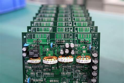
Printed Circuit Boards (PCBs) are the backbone of modern electronics, found in everything from consumer gadgets to industrial machinery. However, electronic components on PCBs are prone to failure due to various factors such as environmental stress, manufacturing defects, electrical overload, and aging. Understanding these failures is crucial for engineers, technicians, and hobbyists to diagnose, repair, and prevent future issues.
This article explores common PCB electronic component failures, their causes, detection methods, and preventive measures.
1. Common PCB Electronic Component Failures
1.1 Resistor Failures
Resistors are passive components that limit current flow. Common failure modes include:
- Open Circuit: Excessive current or overheating can burn out resistors, leading to an open circuit.
- Drift in Resistance Value: Aging or thermal stress can cause resistance values to shift outside tolerance.
- Physical Damage: Mechanical stress or corrosion can break resistor leads.
Detection:
- Use a multimeter to check resistance (infinite resistance indicates an open circuit).
- Visual inspection for discoloration or burn marks.
Prevention:
- Use resistors with appropriate power ratings.
- Avoid excessive current flow.
- Ensure proper soldering to prevent thermal stress.
1.2 Capacitor Failures
Capacitors store and release electrical energy. Common failures include:
- Electrolytic Capacitor Drying Out: Electrolyte evaporation leads to reduced capacitance.
- Leakage or Short Circuit: Dielectric breakdown causes current leakage.
- Bulging or Bursting: Overvoltage or reverse polarity can cause physical damage.
Detection:
- Capacitance meter to check value deviations.
- ESR (Equivalent Series Resistance) meter for high ESR in degraded capacitors.
- Visual inspection for bulging or leakage.
Prevention:
- Use capacitors with proper voltage ratings.
- Avoid reverse polarity in electrolytic capacitors.
- Keep operating temperatures within limits.
1.3 Diode and Transistor Failures
Semiconductor devices like diodes and transistors are sensitive to electrical stress.
Common Failures:
- Short Circuit: Overcurrent or voltage spikes can cause junctions to short.
- Open Circuit: Thermal stress or manufacturing defects may break internal connections.
- Degradation: Repeated high-power switching can weaken performance.
Detection:
- Diode mode on a multimeter (should show forward bias voltage drop).
- Transistor tester or curve tracer for gain and leakage checks.
Prevention:
- Use proper heat sinks.
- Implement overvoltage protection (TVS diodes).
- Avoid exceeding maximum ratings.
1.4 Integrated Circuit (IC) Failures
ICs are complex and can fail due to multiple reasons:
- Latch-Up: Excessive voltage triggers parasitic thyristors, causing a short.
- Electrostatic Discharge (ESD): Static electricity can damage sensitive IC pins.
- Thermal Stress: Overheating leads to bond wire fractures or delamination.
Detection:
- Logic analyzer or oscilloscope for signal integrity checks.
- Thermal imaging for overheating ICs.
- Visual inspection for burnt or cracked packages.
Prevention:
- Use ESD-safe handling procedures.
- Ensure proper PCB cooling (fans, heat sinks).
- Follow manufacturer-recommended operating conditions.
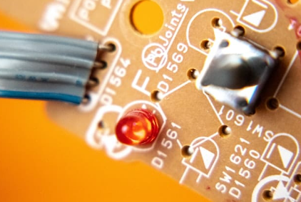
1.5 Connector and Solder Joint Failures
Connectors and solder joints are mechanical weak points.
Common Issues:
- Cold Solder Joints: Poor soldering leads to intermittent connections.
- Corrosion: Moisture exposure causes oxidation.
- Mechanical Fatigue: Repeated plugging/unplugging weakens connectors.
Detection:
- Visual inspection for cracks or discoloration.
- Continuity testing with a multimeter.
- X-ray inspection for hidden solder defects.
Prevention:
- Use high-quality solder and flux.
- Apply conformal coating in humid environments.
- Reinforce high-stress connections with strain relief.
2. Root Causes of PCB Component Failures
2.1 Electrical Overstress (EOS)
- Overvoltage, overcurrent, or incorrect polarity can instantly damage components.
2.2 Thermal Stress
- Repeated heating/cooling cycles cause expansion/contraction, leading to cracks.
2.3 Environmental Factors
- Humidity, dust, and corrosive gases accelerate degradation.
2.4 Manufacturing Defects
- Poor soldering, incorrect component placement, or PCB contamination.
2.5 Aging and Wear-Out
- Electrolytic capacitors, batteries, and mechanical parts degrade over time.
3. Techniques for Detecting PCB Failures
3.1 Visual Inspection
- Look for burnt marks, bulging capacitors, or broken traces.
3.2 Multimeter Testing
- Check continuity, resistance, and diode functionality.
3.3 Oscilloscope Analysis
- Monitor signal integrity and noise issues.
3.4 Thermal Imaging
- Identify overheating components.
3.5 Automated Optical Inspection (AOI)
- High-resolution scanning for manufacturing defects.
4. Preventive Measures
4.1 Proper Design Considerations
- Use derating (operate components below max ratings).
- Implement redundancy for critical circuits.
4.2 Environmental Protection
- Conformal coating to prevent moisture damage.
- Enclosures for dust and vibration resistance.
4.3 Quality Manufacturing Practices
- Automated soldering for consistency.
- Thorough testing before deployment.
4.4 Regular Maintenance
- Periodic inspections and cleaning.
- Replace aging components proactively.
Conclusion
PCB electronic component failures can stem from electrical, thermal, mechanical, or environmental factors. By understanding common failure modes, using proper diagnostic tools, and implementing preventive measures, engineers can enhance PCB reliability and longevity. Regular testing, proper design, and high-quality manufacturing are key to minimizing failures in electronic systems.
By adopting best practices in design, assembly, and maintenance, the lifespan of PCBs can be significantly extended, reducing costly downtime and repairs.


