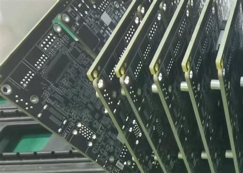
Common PCB Failure Modes and How to Avoid Them
Water is bad news for an operating PCBA. Even small amounts of moisture can cause your board to fail, and avoiding moisture requires the best possible protection methods to be used. Even with this security, your board may still be vulnerable, as several PCB failure modes exist. To build a comprehensive defense, we first need to know why boards fail. We can then define methods to avoid at least the most common PCB failure modes.
Why Do PCBs Fail?
Successfully designing and manufacturing a PCBA (circuit board design for a manufactured or assembled PCB) that reliably meets its performance goals over its lifecycle is always aspirational and definitely achievable. Sometimes it’s easy to overlook the many activities that make it possible. Obviously, depending on the complexity of the board, the design process itself can be long and tedious, and it takes some sound decisions to create a design file package that your contract manufacturer (CM) can build. This is followed by a formal set of manufacturing and fabrication steps, each with some degree of risk. Let’s look at which PCB failure modes are most likely to occur or be detected during assembly and operation.

Common PCB Failure Modes
During Manufacturing
Misaligned Layers
Alignment of the PCB stackup is done during the manufacturing process. However, it may not be discovered before the board is assembled. For example, during manual or optical inspection (AOI). If not detected, opens, shorts, or crossed signal lines may occur, negatively affecting the operation of the board.
Solder Bridges
Solder bridges are unintended connections between conductive elements on a board. These can be between adjacent pads, traces, and closely adjacent pads or traces. Regardless, these can result in shorts and damage to the component or board.
Component Shift
During the assembly process, components are placed before soldering. If components shift or move during the soldering process, quality solder joints will not form, tombstoning or opens may result.
During Operation
Openings
If an open circuit; for example, a separated component forms on the board due to movement or vibration, operation is likely to be erratic and unpredictable. Depending on the function of the board and its larger system, this can be catastrophic. For example, if the board is providing critical measurements, but those measurements are incorrect, the entire system may become unmanageable.
Short Circuits
As opposed to Open Circuits, Short Circuits can cause immediate damage to components or the board itself. If the current level is high enough, a fire can occur on the board. Moisture, undetected solder bridges, creepage, high voltage board breakdown, or unexpected events such as current spikes.
Performance Degradation
The gradual degradation of PCBA performance is one of the most difficult failure modes to detect. In addition, there are many possible root causes. Common problems are:
- Trace degradation – due to poor etching during the manufacturing process.
- Oxidation – due to insufficient or lack of finishing or environmental protection.
- Condensation – caused by moisture diffusion during manufacturing, assembly or storage.
- Incorrect copper weight – improper trace width and size determination.
- Flux corrosion – caused by flux residue used during assembly.
Delamination
Delamination is when the laminate on a board separates from the substrate or dielectric material. The most likely cause is using a CTE that is too low to meet the thermal requirements of the environment in which the board is mounted.
Component functional deterioration
Failure of individual components is also a major concern. Components can fail due to improper selection (function not meeting operational requirements), poor quality, packaging breakage due to overheating, UV exposure, or chemical interactions. Component failure can be gradual or sudden; for example due to shortages.
Board cracking or breaking
PCBAs can also fail due to excessive physical or mechanical stress. For example, a rigid board subjected to repeated shock or vibration may eventually crack or even break. Even flexible boards can break if the flexural strength rating is exceeded.
As mentioned above, your board must retain many potential failure modes in order to meet its lifecycle operational goals. Fortunately, there are decisions that can be made during the design process to improve the likelihood of achieving that goal.
Designing Away PCB Failure Modes
Board failures are often discovered during assembly or operation. Failure modes discovered during assembly often require a redesign before they require a respin and additional cost. If discovered in the field, replacement and/or repair will be required. If a PCB failure mode recurs repeatedly, it may be necessary to stop production and withdraw the deployed boards. In both cases, significant additional costs can be incurred, not to mention increased development time. Obviously, it is best to avoid these unexpected situations, which can most likely be avoided by following the recommended design dos and don’ts listed below.
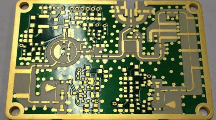
Designing to Avoid and Avoiding Failure Modes
Dos
✅ Choose the Best Materials
One of the most important design decisions is which material to use. While it is common to simply choose a common standard, doing so can result in several PCB failure modes. Instead, you should choose the material that best fits your design based on the material properties and the operational needs of the circuit.
✅ Choose Quality Components
Another important decision to avoid PCB failure modes is choosing components. Component selection should be optimized for your design and carefully crafted to ensure quality and availability.
✅ Choose the Best CM
This is last on the Dos list, but perhaps the most important design decision you make is who will build your boards? Choosing a manufacturing and assembly service can make or break your PCBA development; including turnaround time, board quality, and most importantly, whether or not PCB failure modes occur.
Don’ts
Don’t assume good thermal resistance. Analyze!
Both during manufacturing and in the field, PCBAs must be able to withstand temperature changes, primarily heating. You should never assume that your board will survive these tests unscathed. The best way to ensure that your board will meet the heating requirements of the components and its operating environment is to understand the importance of thermal resistance and perform thermal analysis.
Don’t assume reliability. Test!
Developing a working board is always exciting and it can be tempting to move quickly into production. However, this desire should be tempered by the realization that PCB failure modes in the field can be costly and ruin your relationship with the end user. Therefore, the best and prudent approach is to employ board testing and ensure the reliability of your board.
By following the design guidelines recommended above, you will greatly reduce the likelihood that your board will exhibit PCB failure modes during manufacturing or in the field. However, good design decisions are not enough unless you work with a CM that has the capability and expertise to produce high-quality boards and has established quality processes to do so.

