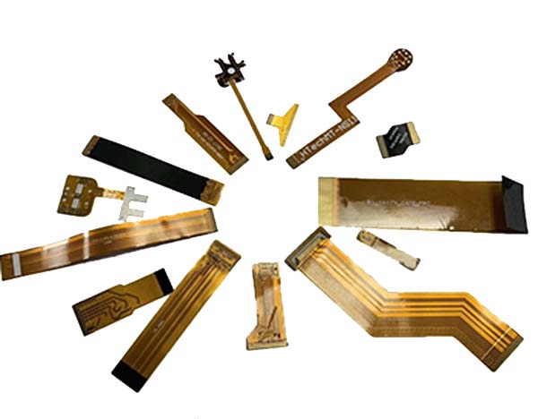
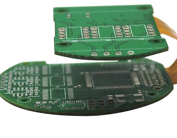
Controlled impedance flex pcb
In modern days, flex circuit boards have become smaller, faster, and more complicated.
Flex boards are typically used in high-frequency applications such as RF communication,
telecommunication, computing using signal frequencies above 100MHz,
high-speed signal processing, and high-quality analog video such as DDR, HDMI, Gigabit Ethernet, etc.
Signal traces have impedance at each point on the signal path. If this impedance varies from point to point,
there will be a signal reflection whose magnitude will depend on the difference between the two impedances.
This reflection will travel in the opposite direction of the signal, which means that the reflected signal will superimpose the original signal.
For a better understanding of controlled impedance read, why controlled impedance really matters?

A controlled impedance flex PCB is a type of flexible printed circuit board (PCB) that is designed to have a specific impedance value for the transmission of high-speed signals.
The impedance of a PCB is the measure of the resistance to the flow of an electrical signal.
In a controlled impedance flex PCB, the impedance is carefully controlled by adjusting the width,
spacing, and thickness of the conductive traces and dielectric layers.
Controlled impedance is important for high-speed digital and analog circuits because it helps to reduce signal reflections, noise, and distortion.
This can improve the overall performance and reliability of the circuit.
Controlled impedance flex PCBs are commonly used in applications such as aerospace, medical devices, telecommunications, and consumer electronics.
To design and manufacture a controlled impedance flex PCB, specialized software and equipment are required.
It is important to work with an experienced and reputable PCB manufacturer who can provide design assistance and ensure that the final product meets the required specifications.

Factors affecting impedance in flex circuit board
Impedance control in flex can be achieved by altering the physical dimensions of the PCB traces and the properties of the dielectric material used.
Below are the factors that affect impedance in flex PCBs.
Physical dimensions of the traces
- Height of the trace
- Width of the top surface of the trace
- Width of the bottom surface of the trace
- Difference between the width at the top of the trace and the bottom of the trace
- Height of the trace from the ground plane
Dielectric properties of the dielectric material used
- The dielectric constant of the dielectric material incorporated
- Dielectric height between the trace and the reference plane
- The dielectric constant of soldermask or coverlay
the role of controlled impedance flex pcb
Controlled impedance flex PCBs play a critical role in high-speed and high-frequency applications,
such as telecommunications, aerospace, and medical devices.
These PCBs are designed to maintain a specific impedance value throughout the entire length of the circuit,
which ensures that the signal is transmitted without any distortion or loss.
The controlled impedance of the flex PCB is achieved by carefully controlling the width, thickness,
and spacing of the conductive traces and the dielectric material between them.
This ensures that the signal travels at a consistent speed and is not affected by any external interference.
Flex PCBs are also used in applications where space is limited, and a rigid PCB cannot be used.
The flexibility of the PCB allows it to be bent or folded to fit into tight spaces,
making it an ideal choice for applications such as wearable devices and medical implants.
Overall, controlled impedance flex PCBs play a critical role in ensuring the reliability and performance of high-speed and high-frequency electronic systems.