Design Trends of Automotive Millimeter-Wave Radar and PCB Material Solutions
Autonomous driving vehicles and advanced driver assistance systems (ADAS) technologies have promoted the rapid development of automotive millimeter-wave radar sensors and the iterative update of technology, making car driving and travel safer.
Millimeter-wave radar has become an indispensable sensor in automotive autonomous driving and ADAS systems due to its advantages of high resolution, strong anti-interference performance, good detection performance, and small size.
With the increasing installation rate of domestic millimeter-wave radar designs and domestic models, the application of millimeter-wave radar has been expanded to more aspects.
This article will briefly explain some application scenarios and design trends of millimeter-wave radars; as well as discuss the selection considerations of key PCB materials in millimeter-wave radar antenna design and the key characteristics of PCB materials.
Application scenarios
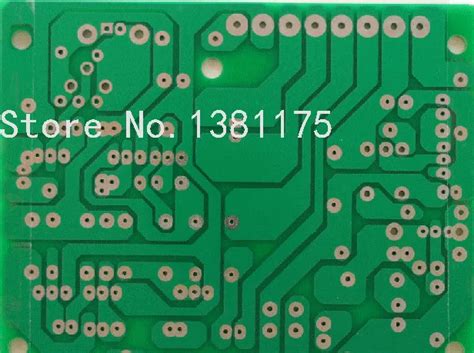
With the development of technology, the evolution of millimeter-wave radars has also followed the direction of meeting user needs, achieving a detection range from near to far, and the measurement accuracy has gradually improved. From the earliest speed and distance measurement, to the realization of speed, distance, and angle measurement, to the current higher resolution image imaging. In ADAS systems, the application of millimeter-wave radar can be divided according to vehicle needs and functions. For example, it can be divided into forward radar, rear radar and corner radar according to the different installation positions on the car; it can also be divided into long-range radar, medium-range radar and short-range radar according to the detection distance. The application of millimeter-wave radar in ADAS includes AEB automatic braking, FCW forward collision warning, LCA lane change assistance, ACC adaptive cruise, BSW blind spot monitoring, etc.
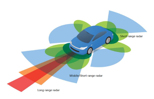
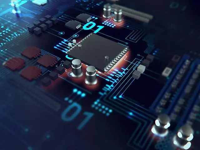
Figure 1 Millimeter-wave radar sensor in ADAS
In addition to assisting the driving and driving safety of the car, the application of automotive millimeter-wave radar has also been extended to the application of obstacle detection when parking or opening the door, reducing the collision damage of the door when parking or opening the door.
Various other applications have increased the diversity of millimeter-wave radar applications and actively expanded new scenarios for millimeter-wave radar applications. For example, the driver’s vital signs monitoring radar sensor can realize non-contact monitoring of the driver’s vital signs, such as heart rate and breathing rate, so as to sense the driver’s fatigue state and achieve the purpose of safe driving. Passenger member monitoring radar sensors also achieve reliable detection of passengers (adults, children, pets) in the car in a non-contact manner, avoiding the occurrence of accidental detention during travel and providing consumers with safe travel protection.
Design Trend
The operating frequencies of automotive millimeter wave radars are mainly 24GHz and 77GHz. The 24GHz band is mainly used for short-range radars with a detection distance of about 50m, which can be used for systems such as blind spot detection. However, due to its narrow bandwidth, the resolution and performance of the radar are greatly limited.
Relatively speaking, the 77GHz radar has broad prospects, and its great advantages are high precision, high resolution and excellent measurability from short to long distances. The two frequency bands of 77GHz radar are 76-77GHz and 77-81GHz, with bandwidths of 1GHz and 4GHz respectively. The huge bandwidth advantage significantly improves resolution and accuracy. On the other hand, due to the high frequency and short wavelength of 77GHz radar, the designed radar transceiver or antenna and other components are smaller, thereby reducing the size of the radar and making it easy to install and hide in the car body. The 77GHz band has gained significant traction in terms of global regulation and industry adoption.
The application of 77GHz millimeter-wave radar corresponds to the advanced stage of automotive automation. With the development of autonomous vehicles and the increase in the installation rate of ADAS, most 24 GHz automotive radar sensors will turn to the 77 GHz band, and its demand and application are gradually increasing.
Figure 2 Market trends of radar sensors in different frequency bands
The 77GHz millimeter-wave radar system module is based on the design of FMCW radar. Most of them use complete single-chip solutions such as TI, Infineon or NXP. The RF front end, signal processing unit and control unit are integrated in the chip to provide multiple signal transmission and reception channels. The PCB board design of the radar module varies according to the different antenna designs of customers, but there are mainly the following methods.
The first one uses ultra-low loss PCB material as the carrier board for the top antenna design. The antenna design usually uses a microstrip patch antenna, and the second layer of the stack is used as the ground layer for the antenna and its feeder. The other PCB materials of the stack are all made of FR-4 material. This design is relatively simple, easy to process and low in cost. However, due to the thin thickness of ultra-low loss PCB materials (usually 0.127mm), it is necessary to pay attention to the effect of copper foil roughness on loss and consistency. At the same time, the narrow feed line of the microstrip patch antenna needs to pay attention to the line width accuracy control of the processing.
The second design method uses dielectric integrated waveguide (SIW) circuits for radar antenna design, and the radar antenna is no longer a microstrip patch antenna. In addition to the antenna, other PCB stacks still use FR-4 materials as radar control and power layers as in the first method. The PCB material used in this SIW antenna design still uses ultra-low loss PCB materials to reduce loss and increase antenna radiation. The thickness of the material is usually thicker than the PCB to increase the bandwidth, and it can also reduce the impact of copper foil roughness, and there are no other problems when processing narrow line widths. However, it is necessary to consider the via processing and position accuracy of SIW.
The third design method is to design a laminated structure of a multilayer board with ultra-low loss materials. Depending on different requirements, ultra-low loss materials may be used in several layers, or all layers may use ultra-low loss materials. This design method greatly increases the flexibility of circuit design, can increase the integration level, and further reduce the size of the radar module. However, the disadvantage is that the cost is relatively high and the processing process is relatively complicated.
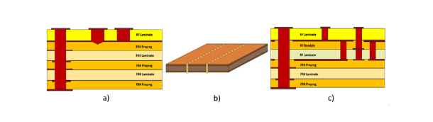
Figure 3 Different PCB designs of radar sensors
Material considerations
For different PCB designs of millimeter-wave radar sensors, there is a common feature that they all need to use ultra-low loss PCB materials to reduce circuit loss and increase antenna radiation. PCB materials are key components in radar sensor design. Choosing the right PCB material ensures that the millimeter-wave radar sensor has high stability and performance consistency.
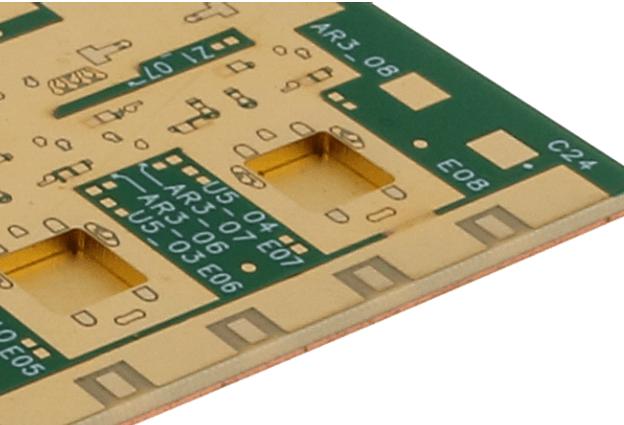
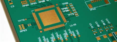
Figure 4 Microstrip antenna for automotive radar sensor
The performance of PCB materials suitable for 77GHz millimeter-wave radar needs to be considered from the following aspects:
First is the electrical properties of the material, which is the primary factor in designing radar sensors and selecting PCB materials. Choosing PCB materials with stable dielectric constants and ultra-low loss is crucial to the performance of 77GHz millimeter-wave radars. Stable dielectric constant and loss can enable the transceiver antenna to obtain accurate phase, thereby improving antenna gain and scanning angle or range, and improving radar detection and positioning accuracy. The stability of the dielectric constant and loss of PCB must not only ensure the stability of different batches of materials, but also ensure that the changes within the same board are small and have very good stability.
The surface roughness of the copper foil used in PCB materials will affect the dielectric constant and loss of the circuit. The thinner the material, the greater the impact of the surface roughness of the copper foil on the circuit. The rougher the type of copper foil, the greater the change in its own roughness, which will also cause a large change in the dielectric constant and loss, affecting the phase characteristics of the circuit.
Secondly, the reliability of the material needs to be considered. The reliability of the material not only refers to the high reliability of the material in terms of superposition, influence of the processing process, vias, copper foil bonding force, etc. in PCB processing, but also includes the long-term reliability of the material. Whether the electrical properties of the PCB material can remain stable over time, and whether it can remain stable in different working environments such as different temperatures or humidity, is self-evidently important for the reliability of automotive radar sensors and the application of automotive ADAS systems.
In general, for the antenna design of 77GHz radar sensors, it is necessary to consider the selection of materials with stable dielectric constants and ultra-low loss. Choosing smoother copper foil can further reduce circuit loss and dielectric constant tolerance changes; at the same time, the material must have reliable electrical and mechanical properties over time, temperature, humidity and other external working environments.
Material selection
Rogers has maintained cooperation with the world’s top radar module manufacturers since the early days of the development of automotive millimeter-wave radars. The performance of the RO3003TM material without glass cloth has been rigorously verified in all aspects and can meet the needs of 77GHz radar sensors. RO3003TM is widely used in 77GHz millimeter-wave radars. RO3003TM has a very stable dielectric constant and ultra-low loss characteristics (the loss factor is 0.001 at 10GHz in conventional tests); at the same time, the structure without glass cloth further reduces the local dielectric constant changes in the millimeter-wave frequency band, eliminates the glass fiber effect of the signal, and further increases the phase stability of the radar sensor. RO3003TM also has ultra-low water absorption characteristics (0.04% @D48/50) and extremely low dielectric constant temperature change (TCDk) stability (-3ppm/°C). These characteristics also ensure that the millimeter-wave radar sensor based on RO3003TM can maintain excellent performance over time, temperature and environmental changes. The various copper foil types and low copper thickness options provided by the product also help to improve processing accuracy and product yield, so that the radar sensor can achieve better performance.
With the development of 79GHz band (77-81GHz) radar sensors, it has a wider signal bandwidth, which can further improve the resolution of radar sensors, increase scanning angles, and even achieve 4D imaging. Based on RO3003TM material, Rogers has developed and launched RO3003G2TM material to match the higher requirements of radar sensors for PCB material performance. Compared with RO3003TM material, RO3003G2TM optimizes the special filler system in the material system, reduces the filler particles, improves the uniformity of the material system, and further reduces the dielectric constant tolerance between the whole board and batches; the smaller and uniform filler system also enables smaller via design during PCB processing; RO3003G2TM material selects smoother copper foil, which reduces the insertion loss in the circuit, and its performance is very close to the rolled copper insertion loss performance of RO3003TM.
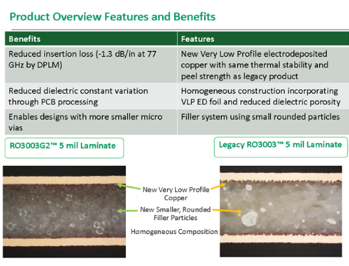
Figure 5 Comparison of RO3003G2TM and RO3003TM materials
In addition, Rogers’ CLTE-MWTM and RO4830TM materials can also meet customers’ different needs in 77GHz radar sensor design. CLTE-MWTM is a material based on PTFE resin system with very small loss factor characteristics (Df 0.0015@10GHz). It is reinforced with special low-loss fiberglass cloth. Together with uniform fillers, it provides excellent dimensional stability and minimizes the influence of glass fiber effect. There are multiple thickness options from 3mil to 10mil, making CLTE-MWTM material very suitable for 77GHz radar sensor RF multilayer board applications.
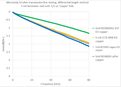
Figure 6 Loss characteristics of different materials
RO4830TM is specially developed based on Rogers RO4000 series material system, and the dielectric constant matches the most commonly used low dielectric constant (Dk) of 77GHz radar sensors. At the same time, it has extremely low insertion loss characteristics and the same easy processing as RO4000® series products. The use of special low-loss fiberglass cloth also improves the performance consistency of the material in the millimeter wave frequency band, allowing the antenna to obtain more consistent phase characteristics and higher antenna gain. RO4830TM is the first choice for cost-effective materials in the design of 77GHz/79GHz radar sensors due to its low cost and high cost performance.
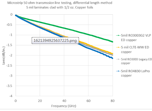
Figure 7 RO4830 fiber-split glass cloth
Summary
The unique advantages of 77GHz millimeter wave radar sensors make them an indispensable component for autonomous vehicles. 77GHz/79GHz radar sensors with wider bandwidth and higher resolution are gradually becoming mainstream. For various radar sensor design schemes, the characteristics of PCB circuit materials determine the performance of radar sensor antennas to a large extent. As a global leader in advanced engineering materials, Rogers Technology is committed to developing various materials to meet customer design needs. RO3003G2TM/RO3003TM/CLTE-MWTM/RO4830TM and other material solutions have solved design problems for customers in a timely manner. At the same time, Rogers’ global customer and technical support teams can ensure closer cooperation with customers, jointly solve a series of problems in design, processing and testing, and accelerate customer design cycles.