Designing a Compact EGS002 Inverter Layout for 12V-220V Conversion

Key Takeaways
When building a compact EGS002 inverter for 12V-220V conversion, start by understanding the module’s core components: the EGS002 driver board, power MOSFETs, and high-frequency transformers. These elements form the backbone of efficient DC-to-AC conversion. To minimize PCB manufacturing cost, prioritize a streamlined layout that reduces material waste and optimizes trace routing. Partnering with established PCB manufacturing companies ensures reliable fabrication while balancing affordability—critical for DIY projects.
For component selection, focus on cost-effective parts like IRF3205 MOSFETs and ferrite-core transformers, which deliver stable performance without overspending. When designing your PCB layout, group high-current paths together and maintain adequate spacing between heat-generating components. This approach not only improves efficiency but also simplifies troubleshooting. Below is a comparison of PCB manufacturing business considerations for small-scale projects:
| Factor | Low-Cost Option | Premium Option |
|---|---|---|
| Turnaround Time | 7-10 days | 3-5 days |
| Minimum Order Quantity | 5 boards | 1 board |
| Cost per Board | $8–$12 | $15–$25 |
Testing is vital for stability. Use a multimeter and oscilloscope to verify 220V AC output and ensure no voltage spikes. Integrate safety features like fuses and overload protection to safeguard both the circuit and user. For heat management, pair aluminum heat sinks with strategic airflow channels, even in tight spaces.
Affordable PCB manufacturing services, such as those offered by AndwinPCBA, enable hobbyists to prototype efficiently. Remember, a well-planned layout reduces PCB manufacturing cost while maximizing reliability—key for off-grid solar setups or portable power solutions. Always adhere to safety protocols, including insulation checks and proper grounding, to ensure long-term operation.

Understanding the EGS002 Inverter Module: Core Components and Functions
The EGS002 inverter module serves as the backbone of your 12V-220V conversion system, integrating critical components that balance performance and space efficiency. At its core, the module combines a high-frequency transformer, MOSFET drivers, and a PWM controller (typically the SG3525 chip) to regulate voltage conversion. The SG3525 generates precise pulse-width modulation signals, controlling the switching frequency of the power MOSFETs, which amplify the 12V DC input to a higher voltage. This amplified signal then passes through the ferrite-core transformer, stepping it up to 220V AC.
When designing your PCB layout, collaboration with PCB manufacturing companies becomes crucial. A compact design requires careful placement of components to minimize electromagnetic interference (EMI) and optimize heat dissipation. For instance, positioning the MOSFETs close to the transformer reduces resistive losses, while separating low-voltage and high-voltage traces prevents cross-talk. To keep PCB manufacturing costs low, prioritize standardized component sizes and avoid overly complex routing. Many DIY builders opt for double-sided boards from affordable PCB manufacturing services, which offer durability without inflating the budget.
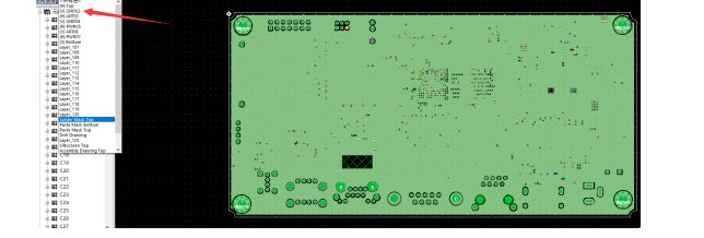
Understanding the interplay between thermal management and component spacing is equally vital. The EGS002 module generates significant heat during operation, so incorporating copper pours or heatsinks into your PCB manufacturing plan ensures long-term reliability. If you’re running a small-scale PCB manufacturing business, prototyping with software like KiCad or Eagle helps visualize thermal pathways and verify clearances before production.
Finally, safety features like overcurrent protection and short-circuit safeguards are embedded in the EGS002’s design. These rely on precise feedback loops between the PWM controller and output stages, which demand clean signal paths in your PCB layout. By balancing cost, efficiency, and safety, you’ll create a robust inverter system that aligns with both DIY practicality and professional PCB manufacturing standards.

Selecting Essential Parts: Cost-Effective Components for DIY Inverter Builds
When assembling a compact EGS002-based inverter, choosing the right components is critical to balancing performance, safety, and affordability. Start with the core module: the EGS002 inverter board, which integrates the driver circuitry and PWM control. Pair this with a high-efficiency ferrite-core transformer rated for 12V-220V conversion, ensuring minimal energy loss during operation. For MOSFETs, opt for IRF3205 or similar models, as they offer low on-resistance and high current-handling capabilities.
Your PCB manufacturing strategy plays a pivotal role in keeping costs low. Collaborate with PCB manufacturing companies specializing in small-batch prototypes to reduce PCB manufacturing cost while maintaining quality. Prioritize double-sided boards with thick copper traces to handle high currents without overheating. When sourcing capacitors, select low-ESR electrolytic types (e.g., 4700µF/25V) for the DC bus and polyester film capacitors for filtering AC output.
Tip: Compare quotes from multiple PCB manufacturing businesses to find a balance between turnaround time and affordability. Many providers offer discounts for bulk orders, which is useful if planning multiple builds.
For resistors, use wire-wound or metal-film variants rated for high power dissipation. A current-limiting resistor (10Ω/5W) on the gate driver protects MOSFETs from voltage spikes. Don’t overlook safety components: fast-acting fuses (10A-15A) on the input side and a Varistor (MOV) across the AC output suppress surges. Enclosures and heat sinks should be lightweight yet durable—aluminum enclosures with integrated cooling fins work well for space-constrained designs.
Finally, consider wire gauge and connectors. 12AWG cables are ideal for primary DC connections, while terminal blocks simplify assembly and maintenance. By prioritizing cost-effective yet reliable parts, you ensure your inverter remains both functional and budget-friendly.
Designing a Compact PCB Layout for Efficient 12V-220V Conversion
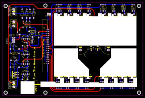
When designing a compact PCB layout for your EGS002-based inverter, start by mapping the placement of critical components to minimize trace lengths and reduce electromagnetic interference (EMI). The EGS002 module acts as the brain of the system, so position it centrally to ensure balanced connections to the MOSFET drivers, transformers, and feedback circuits. Prioritize short, thick traces for high-current paths—such as those between the DC input (12V) and the H-bridge MOSFETs—to reduce resistive losses and heat buildup. Use a ground plane to stabilize voltage references and shield sensitive signals, but avoid creating loops that could amplify noise.
Space constraints demand careful planning. Opt for surface-mount components where possible, as they occupy less board area than through-hole parts. When selecting PCB manufacturing companies, verify their capability to handle fine-pitch soldering and double-sided assembly, which are common in dense layouts. While PCB manufacturing cost is a consideration, prioritize quality to avoid issues like delamination or poor solder joints, which can compromise reliability. For DIY builders, prototyping services from affordable PCB manufacturing providers offer a balance between precision and budget.
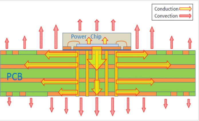
Thermal management is critical in compact designs. Integrate thermal vias beneath high-power components like MOSFETs or transformers to dissipate heat efficiently. If space allows, add small heatsinks or copper pours to act as passive cooling elements. Test the layout using simulation tools to identify hotspots before finalizing the design. This step ensures your PCB manufacturing business or personal project avoids costly revisions post-production.
Finally, adhere to safety standards by maintaining adequate creepage and clearance distances between high-voltage (220V AC) and low-voltage (12V DC) sections. Silkscreen labels for polarity and voltage ratings to prevent wiring errors during assembly. By balancing efficiency, PCB manufacturing practicality, and safety, you’ll create a robust inverter layout that delivers stable AC output without sacrificing space or affordability.
Step-by-Step Assembly Guide: Wiring and Mounting the EGS002 System
Begin by organizing your components, ensuring all parts—such as the EGS002 driver board, MOSFETs, transformers, and capacitors—are readily accessible. Start by mounting the EGS002 module onto your pre-designed PCB layout, aligning its pins carefully with the designated solder pads. A well-planned PCB manufacturing process ensures precise alignment, minimizing errors during assembly. If you’re sourcing parts from PCB manufacturing companies, verify that the board dimensions and trace widths match your design specifications to handle the current demands of 12V-220V conversion.
Next, solder the high-current pathways first, focusing on connections between the MOSFETs and the transformer. Use thick gauge wires or wide copper traces to reduce resistance and heat buildup. For space efficiency, position the transformer close to the MOSFETs, securing it with epoxy or mounting brackets to prevent vibration-related issues. When routing low-voltage control signals, keep them isolated from high-voltage sections to avoid electromagnetic interference.
Pay attention to PCB manufacturing cost optimization by reusing existing board space creatively—for example, placing smaller components like resistors or diodes beneath the transformer. Insulate all exposed connections with heat-shrink tubing or silicone sealant, especially near high-voltage terminals. Double-check solder joints for cold connections or bridges, as these can lead to failures during testing.
If you’re managing a PCB manufacturing business, consider batch-producing boards to reduce per-unit costs while maintaining consistency. Secure the assembled PCB inside a compact, non-conductive enclosure, leaving adequate ventilation around heat-generating components like MOSFETs. Use standoffs or spacers to elevate the board, improving airflow and simplifying future maintenance.
Finally, route input and output cables through strain-relief grommets to protect against wear. Label terminals clearly (e.g., “12V DC Input” and “220V AC Output”) for error-free operation. By prioritizing a methodical approach to wiring and mounting, you’ll ensure a reliable, space-efficient inverter ready for performance testing.
Testing and Troubleshooting: Ensuring Stable AC Output and Safety
After assembling your EGS002-based inverter, rigorous testing is essential to confirm stable 220V AC output and adherence to safety standards. Begin by verifying the 12V DC input using a multimeter, ensuring connections align with your PCB layout. Power the system and measure the AC output with a true-RMS multimeter or oscilloscope to check for a clean sine wave. If the output voltage deviates from 220V AC, inspect feedback resistors or adjust the EGS002 module’s potentiometer, if applicable.
Common issues like voltage spikes or harmonic distortion often stem from improper grounding or inadequate filtering. Double-check solder joints and component placements, especially capacitors and MOSFETs, as loose connections can destabilize the output. Partnering with reliable PCB manufacturing companies ensures your board’s design minimizes noise and heat buildup—critical for maintaining efficiency in compact builds. If overheating occurs, reassess heatsink placement or consider upgrading thermal management components.
Safety testing is non-negotiable. Use an insulation resistance tester to confirm no leakage between live parts and the chassis. Integrate fuses or circuit breakers rated for your system’s current to protect against short circuits. For cost-sensitive projects, balancing PCB manufacturing cost with quality is key; opt for certified suppliers that offer durable materials without inflating expenses.
If troubleshooting persists, cross-reference your PCB manufacturing files with the EGS002 datasheet to rule out design flaws. Some PCB manufacturing businesses provide design review services, helping identify layout inefficiencies before production. Finally, test the inverter under load (e.g., a 100W lamp) to simulate real-world conditions, monitoring voltage stability and temperature rise. By methodically addressing each layer—from component integrity to PCB manufacturing precision—you’ll achieve a reliable, safe, and space-efficient power solution.

Optimizing Heat Management in Space-Constrained Inverter Designs
When designing a compact EGS002-based inverter, managing heat dissipation becomes critical to maintaining efficiency and preventing component failure. Space constraints amplify thermal challenges, as tightly packed circuits restrict airflow and trap heat. Start by selecting PCB manufacturing services that prioritize thermal management features, such as copper thickness optimization or heat-resistant substrates. Reputable PCB manufacturing companies often offer design consultations to address thermal bottlenecks early, ensuring your layout minimizes hotspots while accommodating high-current traces.
Strategic component placement is key—position heat-generating parts like MOSFETs and transformers near the edges of the PCB or close to ventilation points. Integrate thermal vias beneath power components to conduct heat away from critical areas, a technique often recommended by PCB manufacturing experts. For cost-conscious builders, balancing PCB manufacturing cost with performance means opting for aluminum-core boards or adding localized heat sinks instead of expensive full-board cooling solutions.
Passive cooling methods, such as using thermally conductive adhesives or mounting the PCB on a metal chassis, enhance heat distribution without increasing complexity. If active cooling is unavoidable, small fans or Peltier modules can supplement heat dissipation, though they add to the overall footprint. Always validate your thermal design through load testing, monitoring temperature rises under maximum output.
Finally, collaborate with PCB manufacturing businesses that provide rapid prototyping, allowing iterative testing of heat management strategies. By prioritizing thermal efficiency in both component selection and PCB layout, you ensure reliable 12V-220V conversion even in tightly packed designs.
Safety Protocols: Protecting Circuits and Users During Operation
When working with PCB manufacturing for your EGS002 inverter build, prioritizing safety begins with proper circuit isolation and component placement. Start by ensuring all high-voltage traces on the PCB are adequately spaced to prevent arcing, especially in compact designs where PCB manufacturing cost constraints might tempt you to minimize board size. Partnering with reputable PCB manufacturing companies ensures your layout meets industry standards for creepage and clearance distances, critical when converting 12V DC to 220V AC. Use optocouplers to isolate low-voltage control circuits from high-voltage outputs, reducing the risk of feedback surges that could damage components or endanger users.
Grounding is non-negotiable: connect the inverter’s chassis and PCB ground plane to a reliable earth point. Incorporate fast-acting fuses on both input and output sides to interrupt overcurrent scenarios, and include a resettable thermal fuse near power MOSFETs to guard against overheating. For PCB manufacturing business enthusiasts, integrating these protective elements early in the design phase avoids costly revisions later.
When handling live circuits during testing, always use insulated tools and wear protective gear. Verify that all connections are secure before powering up, and employ a digital multimeter to check for unintended shorts. Enclose the assembled unit in a non-conductive, ventilated housing to prevent accidental contact with live parts while maintaining airflow for heat dissipation.
Finally, test your inverter’s safety features under controlled conditions. Use a residual-current device (RCD) on the AC output side to detect leakage currents, and validate that overload protection triggers as intended. By balancing PCB manufacturing precision with robust safety measures, you’ll create a reliable system that safeguards both your circuitry and end-users.
Real-World Applications: Affordable Power Solutions for Home and Off-Grid Use
When building a compact EGS002-based inverter for 12V-220V conversion, you’ll find its practical applications extend far beyond the workbench. This space-efficient design shines in scenarios where affordable power solutions are critical, such as remote cabins, solar-powered setups, or emergency backup systems. By leveraging a well-optimized PCB layout, you ensure the inverter operates reliably in tight spaces—ideal for integrating into existing home energy systems or portable off-grid kits. For instance, pairing the inverter with a small solar array allows you to power essential 220V appliances like LED lights, phone chargers, or even low-wattage refrigerators without relying on grid electricity.
Collaborating with PCB manufacturing companies becomes crucial here, as their expertise ensures your design meets both performance and safety standards. While PCB manufacturing cost can influence your project’s budget, prioritizing a minimalist yet robust layout helps reduce material waste and keeps expenses manageable. If you’re considering scaling production—say, for community-based energy projects—partnering with a PCB manufacturing business specializing in low-volume orders ensures cost-effective replication of your design.
For off-grid applications, the inverter’s compact footprint lets you mount it in unconventional spaces, like utility boxes or vehicle compartments, without sacrificing cooling efficiency. Always test the system under real-world loads to verify stability, especially when powering sensitive electronics. By balancing PCB manufacturing precision with DIY adaptability, you create a versatile tool that bridges the gap between affordability and functionality. Whether you’re retrofitting a rural home or building a mobile power station, this approach ensures your inverter remains a dependable part of sustainable energy solutions. Just remember to source components from reputable suppliers to maintain safety and longevity in all operating conditions.
Conclusion
When designing a compact EGS002-based inverter for 12V-220V conversion, balancing efficiency, safety, and space constraints requires careful planning. By prioritizing a streamlined PCB layout, you ensure optimal signal integrity and minimize energy loss, which is critical for maintaining stable 220V AC output. Collaborating with reliable PCB manufacturing companies can significantly reduce PCB manufacturing cost while maintaining quality, especially when ordering prototypes or small batches. This approach not only supports affordability but also aligns with the needs of a PCB manufacturing business focused on DIY projects.
Your design choices—from component placement to thermal management—directly impact performance in space-constrained builds. For instance, integrating heat sinks and spacing high-current traces appropriately prevents overheating without sacrificing compactness. Testing each stage of assembly, particularly after PCB manufacturing, helps identify issues early, saving time and resources. Remember that safety features like fuses, isolation gaps, and proper grounding are non-negotiable, even in minimalist designs.
Finally, this project underscores the value of leveraging modern PCB manufacturing techniques to create accessible, off-grid power solutions. Whether for home use or remote applications, a well-executed inverter build proves that functionality and affordability can coexist—provided you prioritize precision in both design and execution.
FAQs
How do I ensure proper component spacing in a compact EGS002 inverter layout?
When designing a PCB layout for space efficiency, prioritize grouping high-frequency components like MOSFETs and transformers away from sensitive signal paths. Use PCB manufacturing companies that offer precision etching to maintain clean traces and avoid short circuits in tight spaces.
What factors influence the PCB manufacturing cost for a DIY inverter?
Cost depends on board size, layer count, and material quality. For a budget-friendly build, opt for single-layer FR-4 boards and standard solder masks. Partnering with PCB manufacturing services that specialize in prototyping can reduce expenses for small batches.
Can I reuse an existing PCB design for my 12V-220V inverter?
While possible, modifying existing designs risks compatibility issues with the EGS002 module. Always verify trace widths and thermal management features match your voltage and current requirements. Custom PCB manufacturing ensures optimal performance for your specific build.
How do I test the inverter’s safety before connecting devices?
Use a multimeter to check for stable 220V AC output under load. Insulate high-voltage sections with heat-shrink tubing and ensure proper grounding. Many PCB manufacturing businesses offer testing services to validate board integrity before assembly.
What’s the best way to manage heat in a compact layout?
Integrate aluminum heat sinks on power components and position them near ventilation points. Copper pour areas on the PCB improve thermal dissipation. For high-power builds, consult PCB manufacturing experts to select substrates with higher temperature tolerance.
How reliable are DIY inverters compared to commercial units?
With careful design and quality PCB manufacturing, DIY inverters can match commercial reliability. Focus on robust soldering, component ratings, and adhering to safety protocols. Pre-assembled modules like the EGS002 simplify alignment with industry standards.
Ready to Start Your PCB Project?
For professional-grade boards tailored to your inverter design, please click here to explore services from AndwinPCB. Their expertise in PCB manufacturing ensures precision and affordability for DIY enthusiasts and small-scale projects.