Difference between rigid and flexible pcb
Understanding The Structural Differences Between Rigid And Flexible PCBs
Printed Circuit Boards (PCBs) are the backbone of modern electronic devices, serving as the foundation upon which electronic components are mounted and interconnected. Among the various types of PCBs, rigid and flexible PCBs are the most commonly used, each offering distinct advantages and applications. Understanding the structural differences between these two types of PCBs is crucial for selecting the appropriate one for specific electronic applications.
Rigid PCBs are characterized by their solid, inflexible substrate, typically made from materials such as fiberglass, epoxy, or phenolic.
This rigidity provides a stable platform for mounting components, ensuring that the board maintains its shape and integrity under various conditions. The inflexible nature of rigid PCBs makes them ideal for applications where the board will not be subject to bending or flexing, such as in desktop computers, televisions, and other stationary electronic devices. The robust structure of rigid PCBs also allows for multiple layers, enabling complex circuitry and high-density component placement, which is essential for advanced electronic systems.
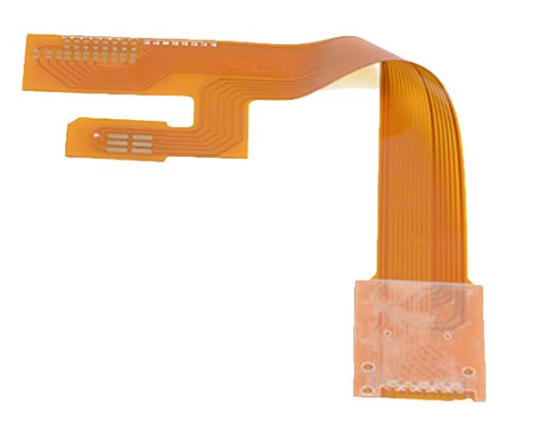
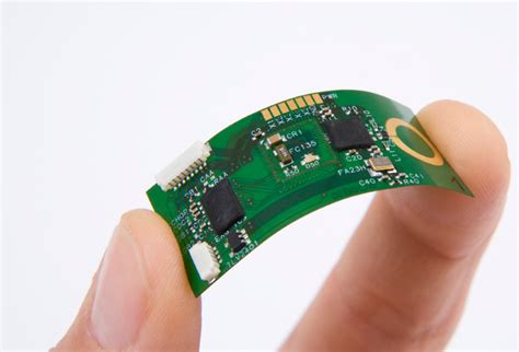
In contrast, flexible PCBs are designed to bend and conform to different shapes, thanks to their use of flexible materials like polyimide or polyester films.
This flexibility allows for innovative design possibilities, making them suitable for applications where space constraints or dynamic movement are factors. For instance, flexible PCBs are commonly used in wearable technology, smartphones, and other portable devices where the board must fit into compact or irregularly shaped spaces. Additionally, the ability to flex without breaking makes these PCBs ideal for applications that require repeated bending, such as in foldable devices or robotic arms.
While both rigid and flexible PCBs serve the fundamental purpose of connecting electronic components, their structural differences lead to distinct manufacturing processes and considerations.
Rigid PCBs are typically manufactured using a subtractive process, where unwanted material is removed to create the desired circuit pattern. This process is well-suited to the stable nature of rigid materials, allowing for precise and reliable circuit formation. On the other hand, flexible PCBs often require an additive process, where conductive materials are deposited onto the flexible substrate. This method accommodates the unique properties of flexible materials, ensuring that the circuits remain intact even when the board is bent or twisted.
Moreover, the choice between rigid and flexible PCBs can significantly impact the overall design and functionality of an electronic device.
Rigid PCBs offer superior mechanical support and are generally more cost-effective for high-volume production, making them a popular choice for consumer electronics. However, their lack of flexibility can be a limitation in applications that demand adaptability and space efficiency. Conversely, flexible PCBs provide unparalleled versatility and can reduce the need for connectors and cables, leading to lighter and more compact designs. Despite these advantages, flexible PCBs can be more expensive to produce and may require specialized handling to prevent damage during assembly.
In conclusion, the structural differences between rigid and flexible PCBs play a pivotal role in determining their suitability for various electronic applications. Rigid PCBs offer stability and cost-effectiveness for stationary devices, while flexible PCBs provide adaptability and space-saving benefits for dynamic and compact designs. By understanding these differences, engineers and designers can make informed decisions that optimize the performance and efficiency of their electronic products.
Applications And Use Cases: Rigid Vs. Flexible PCBs
In the realm of electronic circuit design, the choice between rigid and flexible printed circuit boards (PCBs) is pivotal, as each type offers distinct advantages and is suited to specific applications. Understanding the applications and use cases of rigid versus flexible PCBs is essential for engineers and designers aiming to optimize the performance and reliability of electronic devices.
Rigid PCBs are characterized by their solid, inflexible substrate, typically made from materials like fiberglass.
This rigidity provides a stable platform for mounting components, making them ideal for applications where the board will not be subject to bending or flexing. Consequently, rigid PCBs are commonly found in consumer electronics such as desktop computers, televisions, and home appliances, where the circuit board remains stationary within the device. Their durability and ability to support heavy components make them suitable for these applications, where mechanical stability is paramount.
In contrast, flexible PCBs are constructed from materials like polyimide, which allow them to bend and flex without breaking.
This flexibility opens up a myriad of possibilities for applications where space constraints and dynamic movement are considerations. For instance, flexible PCBs are extensively used in wearable technology, such as smartwatches and fitness trackers, where the circuit must conform to the contours of the human body. Additionally, they are employed in medical devices, including hearing aids and pacemakers, where their ability to fit into compact and irregular spaces is invaluable.
Moreover, the automotive industry benefits significantly from the use of flexible PCBs.
As vehicles become increasingly sophisticated with advanced electronic systems, the need for circuit boards that can withstand vibrations and fit into tight spaces has grown. Flexible PCBs are used in applications such as airbag systems, GPS units, and infotainment systems, where their resilience and adaptability are crucial.
While both rigid and flexible PCBs have their distinct advantages, there are scenarios where a combination of both, known as rigid-flex PCBs, is the optimal solution.
Rigid-flex PCBs integrate the benefits of both types, providing a robust structure with the ability to flex in certain areas. This hybrid approach is particularly useful in aerospace and military applications, where reliability and performance are critical, and space is at a premium. Devices such as satellites and military communication equipment often employ rigid-flex PCBs to achieve the necessary balance between durability and flexibility.
Furthermore, the choice between rigid and flexible PCBs can also be influenced by cost considerations.
Rigid PCBs are generally less expensive to manufacture due to their simpler design and production process. However, the long-term benefits of flexible PCBs, such as reduced weight and space savings, can outweigh the initial cost, especially in high-performance applications.
In conclusion, the decision to use rigid or flexible PCBs hinges on the specific requirements of the application. Rigid PCBs offer stability and are well-suited for static environments, while flexible PCBs provide versatility and adaptability for dynamic and space-constrained applications. By understanding the unique advantages and use cases of each type, engineers can make informed decisions that enhance the functionality and efficiency of electronic devices across various industries.
Manufacturing Processes: How Rigid And Flexible PCBs Are Made
In the realm of electronics, printed circuit boards (PCBs) serve as the backbone of most devices, providing the necessary pathways for electrical currents to flow between components. Among the various types of PCBs, rigid and flexible PCBs are the most prevalent, each offering distinct advantages and manufacturing processes. Understanding the differences in their production is crucial for selecting the appropriate type for specific applications.
Rigid PCBs are the most common type, characterized by their solid, inflexible substrate, typically made from fiberglass-reinforced epoxy resin, such as FR-4.
The manufacturing process for rigid PCBs begins with the creation of a substrate, which involves layering sheets of fiberglass cloth and impregnating them with epoxy resin. This composite is then cured under heat and pressure to form a solid, durable board. Once the substrate is prepared, a thin layer of copper foil is laminated onto its surface. This copper layer is essential for creating the circuit patterns.
The next step involves applying a photosensitive resist to the copper surface, which is then exposed to ultraviolet light through a photomask that outlines the desired circuit pattern. The exposed areas of the resist harden, while the unexposed areas remain soft and are subsequently washed away, revealing the copper beneath. The board is then subjected to an etching process, typically using a chemical solution, to remove the unwanted copper, leaving behind the precise circuit pattern. Finally, the board undergoes a series of finishing processes, including solder mask application and surface finish, to protect the copper traces and prepare the board for component assembly.
In contrast, flexible PCBs are designed to bend and conform to various shapes, making them ideal for applications where space is limited or where the board must endure mechanical stress.
The manufacturing process for flexible PCBs shares some similarities with that of rigid PCBs but involves distinct materials and techniques. The substrate for flexible PCBs is typically made from polyimide, a flexible and heat-resistant polymer. This material is chosen for its ability to withstand bending and flexing without breaking. The copper foil is laminated onto the polyimide substrate using an adhesive, which must be carefully selected to maintain flexibility. The circuit patterning process is similar to that of rigid PCBs, involving the application of a photosensitive resist, exposure to ultraviolet light, and etching to remove excess copper. However, additional steps are often required to enhance the durability and flexibility of the board, such as the application of a flexible solder mask and the use of coverlays, which are protective layers that shield the copper traces while allowing the board to flex.
While both rigid and flexible PCBs serve the fundamental purpose of connecting electronic components, their manufacturing processes reflect their distinct applications and performance requirements.
Rigid PCBs are favored for their durability and cost-effectiveness in applications where space and flexibility are not primary concerns. Conversely, flexible PCBs are indispensable in modern electronics, where compactness and adaptability are paramount. By understanding the differences in their manufacturing processes, engineers and designers can make informed decisions about which type of PCB best suits their specific needs, ultimately enhancing the performance and reliability of their electronic devices.

Cost Considerations: Rigid Versus Flexible PCBs
When evaluating the cost considerations of rigid versus flexible printed circuit boards (PCBs), it is essential to understand the distinct characteristics and applications of each type. Rigid PCBs, as the name suggests, are inflexible and are typically made from solid materials such as fiberglass. They are widely used in applications where the board does not need to bend or flex, such as in desktop computers and televisions. On the other hand, flexible PCBs are made from materials like polyimide, which allow them to bend and conform to different shapes. This flexibility makes them ideal for use in compact and dynamic environments, such as wearable technology and mobile devices.
The cost implications of choosing between rigid and flexible PCBs can be significant, and several factors contribute to these differences.
Initially, the material costs for flexible PCBs are generally higher than those for rigid PCBs. The specialized materials required for flexibility, such as polyimide films and flexible adhesives, tend to be more expensive than the fiberglass and epoxy used in rigid boards. Additionally, the manufacturing process for flexible PCBs is more complex, often involving additional steps such as lamination and etching, which can increase production costs.
However, while the upfront costs of flexible PCBs may be higher, they can offer cost savings in other areas.
For instance, the ability of flexible PCBs to bend and fold can lead to a reduction in the overall size and weight of the electronic device. This can result in lower shipping and handling costs, as well as savings in material costs for the device’s housing. Furthermore, flexible PCBs can reduce the need for connectors and other interconnecting components, which can simplify assembly and reduce labor costs.
In contrast, rigid PCBs are generally more cost-effective for high-volume production runs.
Their straightforward manufacturing process and the widespread availability of materials make them a more economical choice when producing large quantities. Additionally, rigid PCBs tend to have a longer lifespan and greater durability in static applications, which can lead to cost savings over time due to reduced maintenance and replacement needs.
Another consideration is the design complexity associated with each type of PCB.
Flexible PCBs offer greater design versatility, allowing for more innovative and compact product designs. However, this complexity can also lead to increased design and testing costs. Engineers must carefully consider the mechanical and thermal stresses that flexible PCBs will encounter, which can require more extensive prototyping and testing phases. In contrast, the design process for rigid PCBs is typically more straightforward, which can result in lower design costs.
Ultimately, the decision between rigid and flexible PCBs should be guided by the specific requirements of the application and the overall cost-benefit analysis. While flexible PCBs may offer advantages in terms of space savings and design flexibility, rigid PCBs often provide a more economical solution for high-volume, less complex applications. By carefully weighing these factors, manufacturers can make informed decisions that align with their budgetary constraints and performance goals. In conclusion, understanding the cost considerations of rigid versus flexible PCBs is crucial for optimizing both the financial and functional aspects of electronic product development.