Energy and Power PCB: Design, Materials, and Applications
Introduction
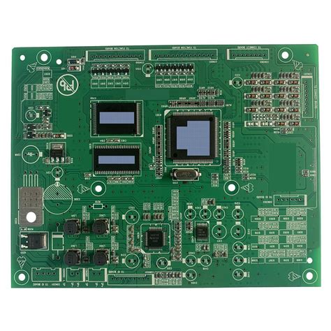
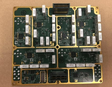
Printed Circuit Boards (PCBs) are essential components in modern electronics, providing mechanical support and electrical connections for various devices. In energy and power applications, PCBs play a critical role in managing high voltages, currents, and thermal dissipation. Energy and power PCBs are used in renewable energy systems, electric vehicles (EVs), industrial motor controls, power supplies, and battery management systems (BMS).
This article explores the key aspects of energy and power PCBs, including design considerations, material selection, thermal management, and applications.
1. Key Design Considerations for Energy and Power PCBs
Designing PCBs for high-power applications requires careful consideration of electrical, thermal, and mechanical factors. Below are the most critical design aspects:
1.1 High Current Handling
Power PCBs must handle high currents without excessive resistive losses or overheating. Key strategies include:
- Wide Traces and Thick Copper Layers: Standard PCBs use 1 oz (35 µm) copper, but power PCBs often require 2 oz (70 µm) or more to reduce resistance.
- Bus Bars and Planes: Instead of thin traces, power PCBs may incorporate bus bars or solid copper planes to distribute high currents efficiently.
- Via Arrays: Multiple vias in parallel help distribute current and reduce localized heating.
1.2 High Voltage Isolation
High-voltage applications (e.g., inverters, power supplies) require proper isolation to prevent arcing and leakage. Design techniques include:
- Creepage and Clearance: Increasing the distance between high-voltage traces to prevent arcing (as per IPC-2221 and IEC 60950 standards).
- Slotting and Cutouts: Adding insulating slots between high-voltage sections to improve dielectric strength.
- High-Dielectric Materials: Using materials with high comparative tracking index (CTI) to resist electrical breakdown.
1.3 Thermal Management
Power electronics generate significant heat, requiring effective thermal dissipation methods:
- Thermal Vias: Placing vias under power components (e.g., MOSFETs, IGBTs) to conduct heat to inner layers or heatsinks.
- Metal-Core PCBs (MCPCBs): Using aluminum or copper substrates for better heat dissipation.
- Heatsinks and Thermal Pads: Attaching external heatsinks or using thermally conductive pads to transfer heat away from critical components.
1.4 EMI and Noise Reduction
High-power circuits can generate electromagnetic interference (EMI), which must be mitigated:
- Proper Grounding: Using a solid ground plane and star grounding techniques to minimize noise.
- Shielding: Adding metal shields or ferrite beads to suppress high-frequency noise.
- Decoupling Capacitors: Placing capacitors near power devices to stabilize voltage and filter noise.

2. Material Selection for Power PCBs
The choice of PCB substrate significantly impacts performance in power applications. Common materials include:
2.1 FR4 (Standard PCB Material)
- Pros: Cost-effective, widely available, suitable for low-to-medium power applications.
- Cons: Limited thermal conductivity (~0.3 W/mK), prone to delamination at high temperatures.
2.2 High-Tg FR4 (Glass Transition Temperature > 170°C)
- Pros: Better thermal stability for high-power applications.
- Cons: Still limited in thermal conductivity compared to metal-core PCBs.
2.3 Metal-Core PCBs (MCPCBs)
- Aluminum-Based (Aluminum-Clad): Excellent thermal conductivity (~1-3 W/mK), lightweight, and cost-effective.
- Copper-Based: Superior thermal performance (~400 W/mK) but heavier and more expensive.
- Applications: LED lighting, motor drives, power converters.
2.4 Ceramic Substrates (Alumina, Aluminum Nitride)
- Pros: Extremely high thermal conductivity (AlN: ~170 W/mK), excellent high-frequency performance.
- Cons: Expensive, brittle, and difficult to manufacture in large sizes.
- Applications: High-power RF, aerospace, and automotive electronics.
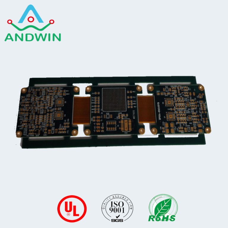
2.5 Flexible and Rigid-Flex PCBs
- Pros: Useful in compact or moving power systems (e.g., EV battery connections).
- Cons: Limited current-carrying capacity compared to rigid boards.
3. Thermal Management Techniques
Since power electronics generate significant heat, effective thermal management is crucial for reliability. Key methods include:
3.1 Heat Sink Integration
- Attached Heatsinks: Extruded aluminum or copper heatsinks mounted on high-power components.
- Integrated Cooling: Some PCBs incorporate liquid cooling channels for extreme power densities.
3.2 Thermal Vias and Planes
- Thermal Vias: Small plated holes that transfer heat from the surface to inner copper layers or the opposite side of the board.
- Copper-Filled Vias: Provide even better heat conduction than standard plated vias.
3.3 Thermal Interface Materials (TIMs)
- Thermal Pads: Silicone-based pads that improve heat transfer to heatsinks.
- Thermal Pastes/Greases: Used between components and heatsinks to fill microscopic air gaps.
3.4 Active Cooling (Fans, Liquid Cooling)
- In high-power applications, forced air or liquid cooling may be necessary to maintain safe operating temperatures.
4. Applications of Energy and Power PCBs
4.1 Renewable Energy Systems
- Solar Inverters: Convert DC from solar panels to AC for grid connection.
- Wind Turbine Controllers: Manage power generation and grid synchronization.
4.2 Electric Vehicles (EVs) and Charging Stations
- Battery Management Systems (BMS): Monitor and balance battery cells for safety and efficiency.
- DC-DC Converters: Step voltage up/down between battery, motor, and auxiliary systems.
- EV Chargers: High-power PCBs manage fast-charging protocols and power delivery.
4.3 Industrial Motor Drives and Power Supplies
- Variable Frequency Drives (VFDs): Control motor speed and efficiency in industrial machines.
- Switched-Mode Power Supplies (SMPS): High-efficiency power conversion for industrial equipment.
4.4 Aerospace and Defense
- Avionics Power Distribution: High-reliability PCBs for aircraft electrical systems.
- Military Power Systems: Ruggedized PCBs for harsh environments.
4.5 Consumer Electronics
- High-Power Amplifiers: Audio and RF amplifiers require robust thermal management.
- Fast Chargers: USB-PD and GaN-based chargers use advanced power PCB designs.
5. Future Trends in Power PCBs
5.1 Wide Bandgap Semiconductors (SiC, GaN)
- Silicon Carbide (SiC) and Gallium Nitride (GaN) devices enable higher efficiency and power density, requiring PCBs with better thermal and high-frequency performance.
5.2 3D-Printed Electronics
- Additive manufacturing allows for custom-shaped PCBs with embedded cooling channels.
5.3 Advanced Thermal Materials
- Graphene-enhanced substrates and diamond-like carbon coatings may improve thermal dissipation.
5.4 Smart PCBs with Embedded Sensors
- PCBs with integrated temperature and current sensors for real-time monitoring and predictive maintenance.
Conclusion
Energy and power PCBs are critical for modern high-performance electronics, enabling efficient power distribution, thermal management, and reliability in demanding applications. Designers must carefully select materials, optimize layouts for high current and voltage, and implement effective cooling strategies.
As technology advances, power PCBs will continue to evolve, supporting next-generation applications in renewable energy, electric vehicles, and industrial automation. By leveraging new materials, semiconductor technologies, and thermal management techniques, engineers can push the limits of power electronics even further.


