Flex pcb design software
Advantages Of Using Flex PCB Design Software
Flex PCB design software has revolutionized the way engineers and designers approach the creation of flexible printed circuit boards.
One of the primary advantages of using such software is the significant enhancement in design efficiency.
Traditional methods of designing PCBs often involve labor-intensive processes that are prone to human error. Flex PCB design software automates many of these tasks, allowing for rapid prototyping and iteration. This not only speeds up the design process but also ensures a higher degree of accuracy, reducing the likelihood of costly mistakes.
Moreover, the software provides a comprehensive suite of tools that facilitate complex design tasks.
For instance, it offers advanced routing capabilities that can handle the intricate pathways required in flexible circuits. These tools are particularly beneficial when dealing with high-density interconnects, where precision is paramount. Additionally, the software often includes simulation features that allow designers to test their circuits in a virtual environment before committing to physical prototypes. This capability is invaluable for identifying potential issues early in the design phase, thereby saving both time and resources.
Another significant advantage is the software’s ability to integrate seamlessly with other design and manufacturing tools.
This interoperability ensures that the transition from design to production is as smooth as possible. For example, many flex PCB design software packages can export files in formats that are readily accepted by manufacturing equipment. This compatibility minimizes the risk of errors during the production phase and ensures that the final product meets the original design specifications.
Furthermore, flex PCB design software often comes with a library of pre-designed components and templates
.These resources can be a tremendous time-saver for designers, as they eliminate the need to create every element from scratch. By leveraging these pre-existing components, designers can focus on the unique aspects of their projects, thereby enhancing creativity and innovation. Additionally, these libraries are frequently updated to include the latest industry standards and components, ensuring that designs are both current and compliant with relevant regulations.
Detailed documentation can be generated automatically
providing a comprehensive record of the design, including component specifications, routing paths, and layer information. This documentation is crucial for both internal review and external compliance audits. Moreover, the reporting features can generate real-time data on various aspects of the design, such as signal integrity and thermal performance. This information is invaluable for making informed decisions throughout the design process.
In addition to these technical advantages, flex PCB design software also offers significant cost benefits. By streamlining the design process and reducing the likelihood of errors, the software can lead to substantial cost savings. These savings are not only realized in the design phase but also extend to manufacturing and post-production. For instance, the ability to simulate and test designs virtually can reduce the need for multiple physical prototypes, thereby lowering material costs. Additionally, the enhanced accuracy and precision of the software can result in fewer defects and rework, further contributing to cost efficiency.
In conclusion, the advantages of using flex PCB design software are manifold. From enhancing design efficiency and accuracy to providing advanced tools and seamless integration with manufacturing processes, the software offers a comprehensive solution for modern PCB design challenges. Its ability to streamline documentation and reporting, coupled with significant cost benefits, makes it an indispensable tool for engineers and designers in the field.
Top Features To Look For In Flex PCB Design Software
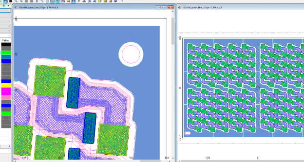
When selecting flex PCB design software, it is crucial to consider several key features that can significantly impact the efficiency and quality of your design process.
One of the primary aspects to evaluate is the software’s user interface.
An intuitive and user-friendly interface can streamline the design process, reducing the learning curve for new users and enhancing productivity for experienced designers. A well-designed interface should offer easy access to essential tools and functions, allowing designers to focus on creativity and precision rather than navigating complex menus.
Another critical feature to look for is the software’s ability to handle complex geometries and flexible materials.
Flex PCBs often require intricate designs that can bend and twist without compromising functionality. Therefore, the software should support advanced design capabilities, including the ability to create and manipulate curved traces, define bend areas, and simulate the mechanical behavior of the flex PCB under various conditions. This ensures that the final product will perform reliably in real-world applications.
In addition to handling complex geometries, the software should offer robust design rule checking (DRC) and electrical rule checking (ERC) capabilities.
These features are essential for identifying potential design issues early in the process, such as spacing violations, signal integrity problems, and other errors that could affect the performance and manufacturability of the flex PCB. By catching these issues early, designers can make necessary adjustments before moving to the prototyping or production stages, saving time and reducing costs.
Furthermore, integration with other design and simulation tools is a valuable feature to consider.
Flex PCB design often involves collaboration with other engineering disciplines, such as mechanical and thermal analysis. Therefore, the ability to seamlessly import and export data between different software platforms can facilitate a more cohesive and efficient design process. This integration can also help ensure that all aspects of the design are thoroughly evaluated and optimized, leading to a higher-quality final product.
Another important consideration is the software’s support for various manufacturing processes and materials.
Flex PCBs can be produced using different techniques and materials, each with its own set of requirements and constraints. The design software should provide comprehensive libraries and templates for different materials and manufacturing processes, enabling designers to select the most appropriate options for their specific application. Additionally, the software should offer tools for generating accurate manufacturing documentation, such as Gerber files and assembly drawings, to ensure a smooth transition from design to production.
Moreover, the ability to perform thermal and mechanical simulations within the design software can be highly beneficial.
Flex PCBs are often used in environments where they are subjected to varying temperatures and mechanical stresses. By simulating these conditions during the design phase, designers can identify potential issues and make necessary adjustments to improve the reliability and durability of the final product. This proactive approach can help prevent costly failures and extend the lifespan of the flex PCB.
Lastly, consider the level of customer support and resources available from the software provider.
Access to comprehensive documentation, tutorials, and technical support can be invaluable, especially when encountering complex design challenges or learning new features. A responsive and knowledgeable support team can help resolve issues quickly, minimizing downtime and ensuring that the design process remains on track.
In conclusion, selecting the right flex PCB design software involves evaluating several key features, including an intuitive user interface, advanced design capabilities, robust rule checking, integration with other tools, support for various manufacturing processes, simulation capabilities, and reliable customer support. By carefully considering these factors, designers can choose a software solution that enhances their productivity, ensures high-quality designs, and ultimately leads to successful flex PCB projects.
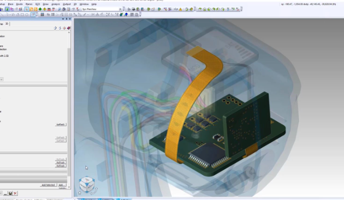
Common Challenges In Flex PCB Design And How Software Can Help
Designing flexible printed circuit boards (flex PCBs) presents a unique set of challenges that can be daunting for engineers and designers. These challenges stem from the inherent flexibility and dynamic nature of flex PCBs, which require careful consideration of material properties, mechanical stresses, and electrical performance. However, advancements in flex PCB design software have significantly mitigated these challenges, providing designers with powerful tools to streamline the design process and enhance the reliability of the final product.
One of the primary challenges in flex PCB design is managing the mechanical stresses that occur during bending and flexing.
Unlike rigid PCBs, flex PCBs must endure repeated mechanical deformation without compromising their structural integrity or electrical performance. This necessitates meticulous planning of the layout to ensure that traces and components are placed in areas that experience minimal stress. Flex PCB design software addresses this issue by offering simulation tools that allow designers to visualize and analyze the mechanical behavior of the board under various conditions. By simulating the bending and flexing processes, designers can identify potential stress points and make necessary adjustments to the layout, thereby enhancing the durability of the final product.
Another significant challenge is the selection of appropriate materials.
Flex PCBs are typically made from polyimide or polyester substrates, which offer the necessary flexibility but also come with their own set of limitations. The choice of materials affects not only the mechanical properties but also the thermal and electrical performance of the PCB. Flex PCB design software assists in this regard by providing comprehensive libraries of materials, complete with detailed specifications and performance characteristics. This enables designers to make informed decisions about material selection, ensuring that the chosen materials meet the specific requirements of the application.
Signal integrity is another critical concern in flex PCB design.
The flexible nature of the substrate can lead to variations in impedance, which can adversely affect signal transmission. Maintaining consistent impedance is crucial for high-speed and high-frequency applications. Flex PCB design software offers advanced tools for impedance control, allowing designers to model and optimize the trace geometry and stack-up configuration. These tools help in achieving the desired impedance levels, thereby ensuring reliable signal transmission and minimizing the risk of signal degradation.
Thermal management is also a key consideration in flex PCB design.
The thin and flexible nature of the substrate can make it challenging to dissipate heat effectively, which can lead to overheating and potential failure of the board. Flex PCB design software provides thermal analysis tools that enable designers to evaluate the thermal performance of the board and identify areas that may require additional cooling measures. By simulating the thermal behavior, designers can implement effective thermal management strategies, such as the use of thermal vias or heat sinks, to ensure the board operates within safe temperature limits.
In addition to these technical challenges, the complexity of flex PCB design often necessitates collaboration among multiple stakeholders, including electrical engineers, mechanical engineers, and manufacturing specialists.
Flex PCB design software facilitates this collaboration by offering integrated platforms that support seamless communication and data sharing. These platforms enable real-time collaboration, allowing team members to work together more efficiently and effectively, thereby reducing the risk of errors and ensuring a smoother design process.
In conclusion, while flex PCB design presents a range of challenges, modern design software offers robust solutions that address these issues comprehensively. By leveraging the advanced tools and features provided by flex PCB design software, designers can overcome the mechanical, material, signal integrity, and thermal challenges, ultimately leading to the development of reliable and high-performance flex PCBs.
Comparing Popular Flex PCB Design Software Tools
Flex PCB design software tools have become indispensable in the electronics industry, offering engineers the ability to create flexible printed circuit boards that are essential for modern, compact, and high-performance devices. As the demand for more sophisticated and miniaturized electronic products grows, the need for advanced design tools that can handle the complexities of flex PCBs has also increased. In this context, comparing popular flex PCB design software tools can provide valuable insights into their capabilities, strengths, and potential limitations.
One of the most widely recognized tools in the industry is Altium Designer.
Known for its comprehensive suite of features, Altium Designer offers robust support for flex and rigid-flex PCB design. Its advanced 3D modeling capabilities allow designers to visualize the final product in a realistic manner, ensuring that all components fit perfectly within the intended form factor. Additionally, Altium Designer’s intuitive user interface and extensive library of components make it a preferred choice for many professionals. However, its high cost can be a barrier for smaller firms or individual designers.
In contrast, KiCad is an open-source alternative that has gained popularity due to its cost-effectiveness and flexibility.
While it may not offer the same level of advanced features as Altium Designer, KiCad provides a solid foundation for flex PCB design. Its modular structure allows users to customize the tool according to their specific needs, and its active community ensures continuous improvements and updates. Nevertheless, the learning curve for KiCad can be steep for beginners, and it may lack some of the more sophisticated functionalities found in commercial software.
Another notable mention is Mentor Graphics’ PADS Professional.
This tool is renowned for its high-performance capabilities and precision in handling complex designs. PADS Professional excels in signal integrity analysis, thermal management, and design rule checks, making it an excellent choice for high-reliability applications. Its integration with other Mentor Graphics tools further enhances its utility, providing a seamless workflow for designers. However, similar to Altium Designer, the cost of PADS Professional can be prohibitive for some users.
Eagle, now part of Autodesk, is another popular choice among PCB designers.
Eagle’s user-friendly interface and extensive component library make it accessible to both novice and experienced designers. Its integration with Autodesk’s Fusion 360 allows for a smooth transition between electronic and mechanical design, facilitating the creation of complex flex PCBs. Despite its advantages, Eagle’s subscription-based pricing model may not appeal to all users, and some may find its feature set less comprehensive compared to other high-end tools.
Lastly, OrCAD by Cadence is a powerful tool that offers a wide range of features tailored for flex PCB design.
OrCAD’s strength lies in its simulation capabilities, which enable designers to test and validate their designs before manufacturing. Its robust design rule checking and constraint management ensure that the final product meets all necessary specifications. However, OrCAD’s complexity can be daunting for new users, and its cost may be a consideration for smaller projects.
In conclusion, the choice of flex PCB design software depends on various factors, including the specific requirements of the project, budget constraints, and the user’s level of expertise. While Altium Designer and PADS Professional offer advanced features and high performance, their cost may be a limiting factor. On the other hand, KiCad and Eagle provide more affordable options with a reasonable set of features, though they may require additional effort to master. OrCAD stands out for its simulation and validation capabilities but may be more suitable for experienced users. Ultimately, selecting the right tool involves balancing these considerations to achieve the best possible outcome for flex PCB design projects.


