Flex pcb limitations
Material Constraints in Flex PCB Design
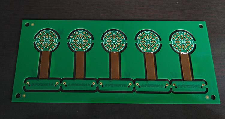
In the realm of modern electronics, flexible printed circuit boards (PCBs) have emerged as a pivotal innovation, offering unparalleled versatility and adaptability. However, despite their numerous advantages, flex PCBs are not without their limitations, particularly when it comes to material constraints. Understanding these constraints is crucial for engineers and designers who aim to optimize the performance and reliability of their electronic devices.
To begin with, the choice of materials in flex PCB design is inherently limited by the need for flexibility and durability.
Unlike rigid PCBs, which can utilize a wide range of materials, flex PCBs must rely on substrates that can withstand repeated bending and flexing. Polyimide is the most commonly used material due to its excellent thermal stability and mechanical properties. However, its cost can be prohibitive, especially for large-scale production. This necessitates a careful balance between performance requirements and budgetary constraints, often leading designers to explore alternative materials such as polyester, which, while more affordable, may not offer the same level of thermal resistance.
Moreover, the adhesive materials used in flex PCBs also present significant limitations.
Adhesives are crucial for bonding the various layers of the PCB, but they must be chosen with care to ensure they do not compromise the board’s flexibility. Traditional adhesives can become brittle over time, especially when exposed to high temperatures, leading to potential failures in the circuit. Consequently, designers often opt for flexible adhesives that can maintain their integrity under stress. However, these specialized adhesives can add to the overall cost and complexity of the manufacturing process.
In addition to substrate and adhesive constraints, the choice of conductive materials is another critical consideration.
Copper is the standard choice for conductive traces due to its excellent electrical properties. However, the thickness of the copper layer must be carefully controlled to maintain flexibility. Thicker copper layers can enhance current-carrying capacity but at the expense of flexibility, potentially leading to cracking or delamination during repeated bending. This trade-off necessitates precise engineering to ensure that the flex PCB can meet both electrical and mechanical requirements.
Furthermore, environmental factors can exacerbate material limitations in flex PCBs.
Exposure to moisture, chemicals, and extreme temperatures can degrade materials over time, affecting the board’s performance and longevity. Protective coatings and encapsulants can mitigate some of these effects, but they add additional layers and weight, which may not be desirable in applications where space and weight are critical considerations.
Finally, the manufacturing process itself imposes constraints on material selection.
Flex PCBs require specialized fabrication techniques, such as roll-to-roll processing, which can limit the types of materials that can be effectively used. The need for precision in cutting and layering also means that any material inconsistencies can lead to defects, further complicating the design and production process.
In conclusion, while flex PCBs offer significant advantages in terms of design flexibility and application versatility, they are subject to a range of material constraints that must be carefully managed. By understanding these limitations, designers can make informed decisions that balance performance, cost, and reliability, ultimately leading to more robust and efficient electronic devices. As technology continues to evolve, ongoing research and development in materials science will likely expand the possibilities for flex PCB design, offering new solutions to these enduring challenges.
Challenges in Flex PCB Manufacturing Processes
Flex PCBs, or flexible printed circuit boards, have become increasingly popular in various industries due to their ability to bend and conform to different shapes, offering significant advantages over traditional rigid PCBs. However, despite their versatility and adaptability, the manufacturing processes of flex PCBs present several challenges that can impact their performance and reliability. Understanding these limitations is crucial for engineers and manufacturers aiming to optimize their use in electronic devices.
One of the primary challenges in flex PCB manufacturing is the material selection.
Flex PCBs are typically made from polyimide or polyester films, which provide the necessary flexibility. However, these materials can be more expensive than those used in rigid PCBs, and their properties can vary significantly depending on the supplier. This variability can lead to inconsistencies in the final product, affecting its mechanical and electrical performance. Moreover, the thinness of these materials, while advantageous for flexibility, can also make them more susceptible to damage during handling and assembly.
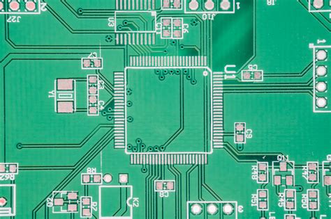
In addition to material challenges, the manufacturing process itself poses several difficulties.
The etching process, which is used to create the circuit patterns on the flex PCB, must be carefully controlled to prevent over-etching or under-etching. Over-etching can lead to breaks in the circuit, while under-etching can cause short circuits. Both issues can compromise the functionality of the PCB. Furthermore, the lamination process, which involves bonding multiple layers of the flex PCB together, requires precise temperature and pressure control. Any deviation from the optimal conditions can result in delamination or misalignment of the layers, leading to potential failures in the field.
Another significant challenge is the soldering process.
Flex PCBs often require surface mount technology (SMT) for component attachment, which involves soldering components onto the board. The flexible nature of the substrate can make it difficult to maintain the necessary flatness during soldering, leading to issues such as tombstoning or insufficient solder joints. Additionally, the thermal expansion properties of the flex materials differ from those of the components, which can cause stress and potential damage during thermal cycling.
Moreover, the testing and inspection of flex PCBs can be more complex than for rigid PCBs.
The flexibility of the board can make it difficult to use traditional testing methods, such as in-circuit testing (ICT) or automated optical inspection (AOI). Specialized equipment and techniques may be required to ensure the integrity and functionality of the flex PCB, adding to the overall cost and complexity of the manufacturing process.
Despite these challenges, advancements in technology and manufacturing techniques continue to improve the reliability and performance of flex PCBs.
Innovations such as laser direct imaging (LDI) and advanced soldering techniques are helping to address some of the limitations associated with flex PCB manufacturing. However, it remains essential for manufacturers to carefully consider these challenges during the design and production phases to ensure the successful implementation of flex PCBs in their applications.
In conclusion, while flex PCBs offer numerous advantages in terms of design flexibility and space savings, their manufacturing processes present several challenges that must be addressed to ensure their reliability and performance. By understanding and mitigating these limitations, manufacturers can better harness the potential of flex PCBs in a wide range of electronic applications.
Durability and Reliability Issues in Flex PCBs
Flexible printed circuit boards (flex PCBs) have become increasingly popular in various industries due to their ability to bend and conform to different shapes, offering significant advantages in terms of design flexibility and space-saving. However, despite these benefits, flex PCBs are not without their limitations, particularly concerning durability and reliability. Understanding these issues is crucial for engineers and designers who aim to optimize the performance and longevity of their electronic devices.
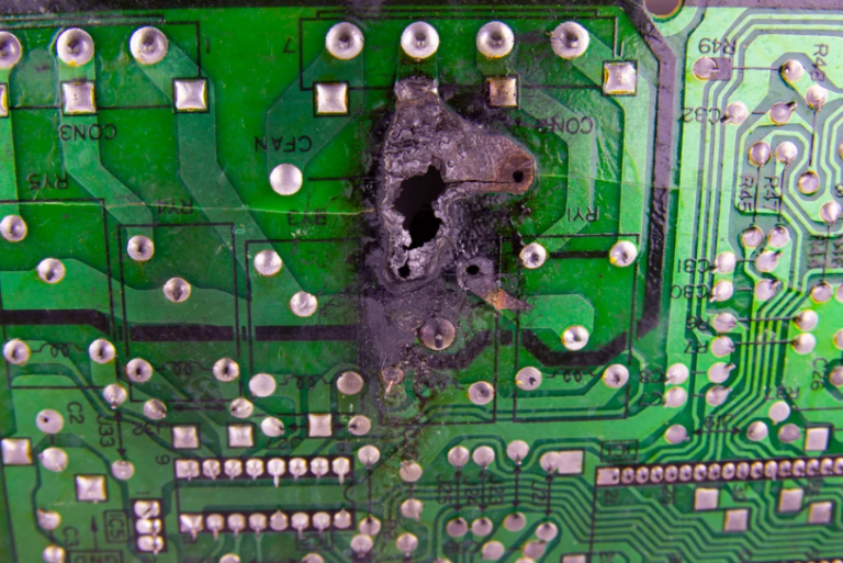
One of the primary concerns with flex PCBs is their susceptibility to mechanical stress.
Unlike rigid PCBs, flex PCBs are designed to bend and flex, which can lead to mechanical fatigue over time. This repeated bending can cause micro-cracks in the conductive traces or the substrate material, potentially leading to circuit failure. To mitigate this risk, it is essential to carefully consider the bending radius and frequency of flexing during the design phase. Employing materials with higher fatigue resistance and optimizing the layout to minimize stress concentration can also enhance durability.
In addition to mechanical stress, environmental factors can significantly impact the reliability of flex PCBs.
Exposure to extreme temperatures, humidity, and corrosive environments can degrade the materials used in flex PCBs, leading to delamination, oxidation, or other forms of deterioration. For instance, high temperatures can cause the adhesive layers to weaken, while moisture can infiltrate the layers, leading to short circuits or corrosion. To address these challenges, selecting materials with appropriate thermal and moisture resistance is vital. Furthermore, incorporating protective coatings or encapsulation can provide an additional barrier against environmental damage.
Another limitation of flex PCBs is their relatively lower thermal management capabilities compared to rigid PCBs.
The thin and flexible nature of these boards can make it difficult to dissipate heat effectively, which is a critical consideration in high-power applications. Excessive heat can accelerate material degradation and increase the risk of failure. To improve thermal management, designers can incorporate thermal vias, heat sinks, or employ materials with better thermal conductivity. Additionally, optimizing the layout to distribute heat-generating components evenly can help maintain a stable operating temperature.
Moreover, the manufacturing process of flex PCBs can introduce potential reliability issues.
The complexity of producing these boards, which involves multiple layers and precise alignment, can lead to defects such as misalignment, incomplete etching, or poor adhesion between layers. These defects can compromise the electrical performance and mechanical integrity of the board. Therefore, stringent quality control measures and advanced manufacturing techniques are essential to ensure the reliability of flex PCBs. Employing automated optical inspection and testing procedures can help identify and rectify defects early in the production process.
Despite these challenges, advancements in materials science and manufacturing technologies continue to improve the durability and reliability of flex PCBs.
Innovations such as the development of new substrate materials, improved adhesives, and enhanced protective coatings are helping to address some of the inherent limitations. Additionally, ongoing research into flexible electronics is paving the way for more robust and reliable flex PCB designs.
In conclusion, while flex PCBs offer significant advantages in terms of design flexibility and space efficiency, they also present unique challenges related to durability and reliability. By understanding and addressing these limitations through careful design, material selection, and manufacturing practices, engineers can enhance the performance and longevity of flex PCBs, ensuring their successful integration into a wide range of applications.
Cost Implications of Flex PCB Limitations
Flex PCBs, or flexible printed circuit boards, have become increasingly popular in various industries due to their ability to bend and conform to different shapes, offering significant advantages over traditional rigid PCBs. However, despite their versatility and adaptability, flex PCBs come with certain limitations that can have cost implications for manufacturers and end-users alike. Understanding these limitations is crucial for making informed decisions about their use in specific applications.
One of the primary cost implications of flex PCB limitations is the increased expense associated with their manufacturing process.
Unlike rigid PCBs, which are typically produced using well-established and cost-effective methods, flex PCBs require specialized materials and processes. The use of flexible substrates, such as polyimide or polyester, and the need for precise handling to avoid damage during production contribute to higher manufacturing costs. Additionally, the complexity of designing circuits that can withstand repeated flexing without failure necessitates advanced engineering expertise, further driving up costs.
Moreover, the limitations in the material properties of flex PCBs can also lead to increased expenses.
For instance, while flex PCBs are designed to be flexible, they are not immune to mechanical stress and can suffer from issues such as delamination or cracking if bent beyond their specified limits. This necessitates rigorous testing and quality assurance processes to ensure reliability, adding to the overall cost. Furthermore, the thermal management of flex PCBs can be challenging, as their thin and flexible nature makes them more susceptible to heat-related issues. This often requires the incorporation of additional cooling solutions or the use of more expensive materials with better thermal properties, both of which can increase costs.
In addition to manufacturing and material considerations, the design limitations of flex PCBs can also have financial implications.
The need to accommodate the unique properties of flexible circuits often results in more complex and time-consuming design processes. Engineers must carefully consider factors such as bend radius, dynamic flexing requirements, and the potential for signal integrity issues, all of which can extend the design phase and increase development costs. Furthermore, the iterative nature of designing flex PCBs, which may involve multiple prototypes and testing cycles to achieve the desired performance, can further escalate expenses.
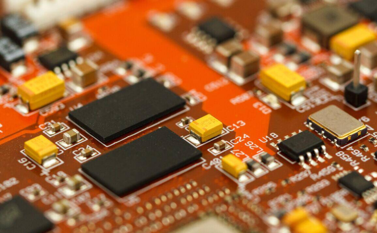
Another aspect to consider is the potential for increased costs related to assembly and integration.
Flex PCBs often require specialized assembly techniques, such as surface mount technology (SMT) or through-hole technology (THT), which can be more expensive than those used for rigid PCBs. Additionally, the need for custom connectors or enclosures to accommodate the unique form factor of flex PCBs can add to the overall cost of the final product. These additional expenses must be weighed against the benefits of using flex PCBs in specific applications to determine their cost-effectiveness.
In conclusion, while flex PCBs offer numerous advantages in terms of design flexibility and space-saving capabilities, their limitations can have significant cost implications.
The increased manufacturing expenses, material challenges, design complexities, and assembly requirements all contribute to the overall cost of using flex PCBs. Therefore, it is essential for manufacturers and designers to carefully evaluate these factors when considering the implementation of flex PCBs in their products, ensuring that the benefits outweigh the associated costs. By doing so, they can make informed decisions that optimize both performance and budgetary considerations.