Flex pcb testing
Importance Of Flex PCB Testing In Modern Electronics
In the rapidly evolving landscape of modern electronics, the importance of flex PCB (Printed Circuit Board) testing cannot be overstated.
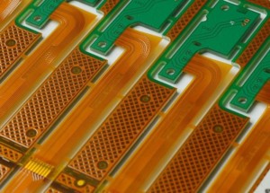
Flex PCBs, known for their ability to bend and conform to various shapes, have become integral components in a wide array of applications, from consumer electronics to medical devices and aerospace technology. As these applications demand higher reliability and performance, ensuring the integrity and functionality of flex PCBs through rigorous testing has become paramount.
To begin with, flex PCBs offer several advantages over traditional rigid PCBs, including reduced weight, space savings, and enhanced durability.
These benefits make them ideal for use in compact and complex electronic devices. However, the very properties that make flex PCBs advantageous also introduce unique challenges in their design and manufacturing processes. The flexibility and thinness of these circuits can lead to issues such as signal integrity problems, mechanical stress, and potential damage during handling and assembly. Consequently, thorough testing is essential to identify and mitigate these risks.
One of the primary reasons for the critical nature of flex PCB testing is the need to ensure electrical performance.
Flex PCBs are often used in high-frequency applications where signal integrity is crucial. Any defects or inconsistencies in the PCB can lead to signal loss, interference, or degradation, which can compromise the overall functionality of the device. Testing methodologies such as impedance testing, time-domain reflectometry (TDR), and signal integrity analysis are employed to verify that the flex PCB meets the required electrical specifications and performs reliably under various operating conditions.
Moreover, mechanical reliability is another key aspect that necessitates comprehensive testing of flex PCBs.
These circuits are frequently subjected to bending, twisting, and other forms of mechanical stress during their lifecycle. Without proper testing, there is a risk of cracks, delamination, or other forms of mechanical failure that can render the device inoperable. Flexural endurance testing, thermal cycling, and environmental stress testing are some of the methods used to evaluate the mechanical robustness of flex PCBs. These tests simulate real-world conditions to ensure that the PCB can withstand the demands of its intended application.
In addition to electrical and mechanical testing, visual inspection and automated optical inspection (AOI) play a crucial role in identifying manufacturing defects such as misalignments, soldering issues, and surface contamination. These inspections are vital for maintaining high-quality standards and preventing defective products from reaching the market. By detecting and addressing these issues early in the production process, manufacturers can reduce the likelihood of costly recalls and warranty claims.
Furthermore, as the complexity of electronic devices continues to increase, the integration of flex PCBs with other components such as rigid PCBs, connectors, and sensors becomes more intricate.
This integration necessitates additional testing to ensure seamless interoperability and compatibility. Functional testing, which involves verifying the overall performance of the assembled device, is essential to confirm that all components work together as intended.
In conclusion, the importance of flex PCB testing in modern electronics is underscored by the need to ensure reliability, performance, and quality in increasingly sophisticated applications. Through a combination of electrical, mechanical, and visual testing methodologies, manufacturers can identify and address potential issues, thereby enhancing the durability and functionality of their products. As technology continues to advance, the role of flex PCB testing will remain a critical factor in the successful development and deployment of cutting-edge electronic devices.
Common Methods For Flex PCB Testing
Flex PCB testing is a critical aspect of ensuring the reliability and performance of flexible printed circuit boards, which are increasingly used in various high-tech applications due to their versatility and space-saving advantages. To guarantee that these PCBs meet stringent quality standards, several common methods are employed during the testing phase. These methods are designed to identify potential defects and ensure that the flex PCBs can withstand the mechanical and electrical stresses they will encounter in real-world applications.
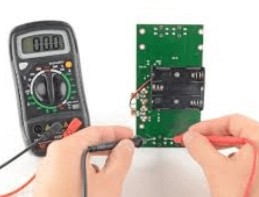
One of the primary methods for testing flex PCBs is the electrical test, which involves checking for continuity and isolation.
Continuity testing ensures that all electrical connections are intact and that there are no open circuits, while isolation testing verifies that there are no unintended connections between different conductive paths. These tests are typically performed using automated test equipment (ATE) that can quickly and accurately assess the electrical integrity of the PCB.
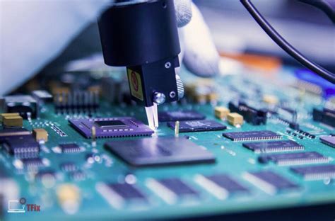
In addition to electrical testing, visual inspection is another fundamental method used to identify defects in flex PCBs.
This process can be conducted manually by trained inspectors or through automated optical inspection (AOI) systems. AOI systems use high-resolution cameras and sophisticated algorithms to detect issues such as misaligned components, soldering defects, and surface contamination. By catching these defects early in the production process, manufacturers can prevent costly rework and ensure higher yields.
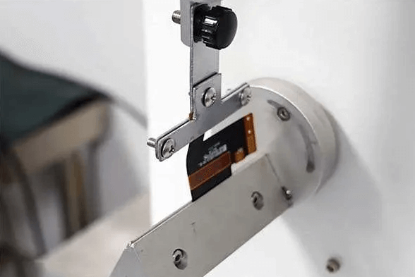
Mechanical testing is also crucial for flex PCBs, given their unique ability to bend and flex.
One common mechanical test is the bend test, which evaluates the PCB’s ability to withstand repeated bending without breaking or losing functionality. This test simulates the conditions the PCB will face in its final application, ensuring that it can endure the mechanical stresses it will encounter. Another important mechanical test is the pull test, which measures the strength of the solder joints and the adhesion of the components to the PCB. This test helps ensure that the components will remain securely attached even under mechanical stress.
Thermal testing is another essential method for flex PCB testing, as these boards often operate in environments with varying temperatures.
Thermal cycling tests expose the PCB to extreme temperature changes, cycling between high and low temperatures to assess its ability to withstand thermal stress. This test helps identify potential issues such as delamination, cracking, and changes in electrical performance that can occur due to thermal expansion and contraction. Additionally, thermal shock testing subjects the PCB to rapid temperature changes, further evaluating its resilience to thermal stress.
Environmental testing is also employed to ensure that flex PCBs can perform reliably under various environmental conditions.
This includes humidity testing, which exposes the PCB to high levels of moisture to assess its resistance to corrosion and other moisture-related issues. Salt spray testing is another environmental test that evaluates the PCB’s ability to withstand corrosive environments, such as those found in marine or industrial applications.
In conclusion, the common methods for flex PCB testing encompass a range of electrical, visual, mechanical, thermal, and environmental tests. Each of these methods plays a vital role in ensuring that the flex PCBs meet the required quality standards and can perform reliably in their intended applications. By employing these comprehensive testing methods, manufacturers can identify and address potential issues early in the production process, ultimately delivering high-quality, reliable flex PCBs to their customers.
Challenges And Solutions In Flex PCB Testing
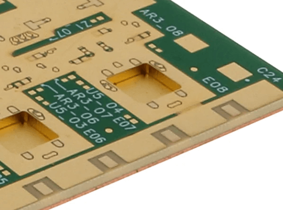
Flex PCB testing presents a unique set of challenges and solutions that are critical to ensuring the reliability and performance of flexible printed circuit boards. These flexible circuits, which are increasingly used in a variety of applications from consumer electronics to medical devices, require rigorous testing to meet the high standards of modern technology. The inherent flexibility and thinness of these PCBs introduce complexities that are not typically encountered with rigid PCBs, necessitating specialized testing methodologies.
One of the primary challenges in flex PCB testing is the mechanical stress that these circuits endure during both the manufacturing process and their operational life.
Flex PCBs are designed to bend and twist, which can lead to potential issues such as micro-cracks, delamination, and conductor breakage. To address these concerns, it is essential to employ dynamic flex testing, which simulates the real-world conditions that the PCB will face. This type of testing involves repeatedly bending the PCB to ensure that it can withstand the mechanical stresses without failure.
Another significant challenge is the thermal management of flex PCBs.
Due to their thin and flexible nature, these circuits can be more susceptible to thermal expansion and contraction, which can affect their performance and longevity. Thermal cycling tests are crucial in this context, as they expose the PCB to extreme temperature variations to evaluate its resilience. By subjecting the PCB to cycles of heating and cooling, manufacturers can identify potential weaknesses and make necessary adjustments to the design or materials used.
Electrical testing also poses unique challenges for flex PCBs.
The flexible nature of these circuits can lead to variations in electrical performance, particularly in high-frequency applications. Impedance control is a critical factor, as any deviation can result in signal integrity issues. To mitigate this, time-domain reflectometry (TDR) and vector network analysis (VNA) are employed to measure and analyze the impedance characteristics of the flex PCB. These advanced testing techniques help ensure that the PCB meets the required electrical specifications and performs reliably in its intended application.
Moreover, the inspection of flex PCBs requires specialized equipment and techniques.
Traditional optical inspection methods may not be sufficient due to the complex geometries and potential for hidden defects within the layers of the flexible circuit. X-ray inspection and automated optical inspection (AOI) systems are often used to detect defects such as voids, misalignments, and solder joint issues. These non-destructive testing methods provide a comprehensive view of the PCB’s integrity without causing any damage.
In addition to these technical challenges, there are also logistical considerations in flex PCB testing.
The handling and fixturing of flexible circuits can be more complicated than rigid PCBs, requiring custom fixtures and careful manipulation to avoid damage. Automated test equipment (ATE) must be adapted to accommodate the unique form factor of flex PCBs, ensuring accurate and repeatable testing results.
In conclusion, the testing of flex PCBs involves addressing a range of mechanical, thermal, electrical, and inspection challenges. By employing specialized testing methodologies and advanced equipment, manufacturers can ensure the reliability and performance of these versatile circuits. As the demand for flexible electronics continues to grow, ongoing advancements in testing techniques will be essential to meet the evolving requirements of this dynamic field.
Innovations In Flex PCB Testing Technology
Flex PCB testing has undergone significant advancements in recent years, driven by the increasing complexity and miniaturization of electronic devices. As flexible printed circuit boards (PCBs) become more integral to modern technology, ensuring their reliability and performance is paramount. Innovations in flex PCB testing technology have emerged to address these challenges, offering more precise, efficient, and comprehensive testing solutions.
One of the most notable advancements in flex PCB testing is the development of automated optical inspection (AOI) systems.
These systems utilize high-resolution cameras and sophisticated algorithms to detect defects such as open circuits, short circuits, and misalignments. By automating the inspection process, AOI systems significantly reduce the time and labor required for manual inspections, while also increasing the accuracy and consistency of defect detection. This innovation is particularly beneficial for high-volume production environments, where speed and precision are critical.
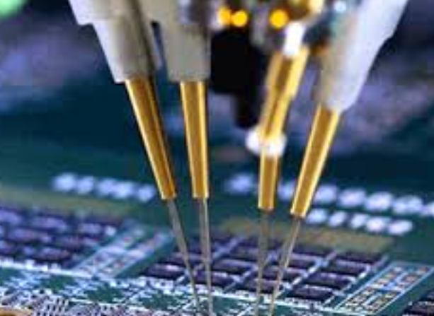
In addition to AOI, advancements in electrical testing methods have also played a crucial role in enhancing flex PCB testing.
Traditional methods, such as flying probe testing, have been refined to accommodate the unique characteristics of flexible circuits. Flying probe testers now feature more advanced probing techniques and improved software algorithms, allowing for faster and more accurate testing of complex flex PCBs. These improvements enable manufacturers to identify electrical faults more efficiently, ensuring that only high-quality boards proceed to the next stage of production.
Moreover, the integration of machine learning and artificial intelligence (AI) into flex PCB testing has opened new avenues for innovation.
Machine learning algorithms can analyze vast amounts of test data to identify patterns and predict potential defects. This predictive capability allows manufacturers to proactively address issues before they become critical, thereby reducing the likelihood of costly recalls and product failures. AI-driven testing systems can also adapt to new designs and manufacturing processes more quickly, providing a flexible and scalable solution for the ever-evolving electronics industry.
Thermal imaging technology has also made significant strides in flex PCB testing.
By capturing detailed thermal profiles of PCBs during operation, thermal imaging systems can identify hotspots and areas of excessive heat generation. These insights are invaluable for assessing the thermal performance and reliability of flex PCBs, particularly in applications where heat dissipation is a critical concern. The ability to detect thermal anomalies early in the testing process helps manufacturers make informed design adjustments and improve the overall performance of their products.
Furthermore, the advent of non-destructive testing (NDT) techniques has revolutionized the way flex PCBs are evaluated.
Methods such as X-ray inspection and ultrasonic testing allow for the examination of internal structures without damaging the board. X-ray inspection, for instance, can reveal hidden defects such as voids, delaminations, and solder joint issues that are not visible through traditional inspection methods. Ultrasonic testing, on the other hand, uses high-frequency sound waves to detect internal flaws and measure material properties. These NDT techniques provide a comprehensive understanding of the structural integrity of flex PCBs, ensuring that they meet stringent quality standards.
In conclusion, the innovations in flex PCB testing technology have significantly enhanced the ability to ensure the reliability and performance of these critical components. Automated optical inspection, advanced electrical testing methods, machine learning, thermal imaging, and non-destructive testing techniques have all contributed to more efficient and accurate testing processes. As the demand for flexible electronics continues to grow, these technological advancements will play an essential role in supporting the development of high-quality, reliable flex PCBs.