Flex pcb trace width
The trace width on a flexible PCB (flex PCB) depends on the current carrying capacity of the trace and the thickness of the copper layer.
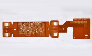
Generally, the trace width on a flex PCB is smaller than that on a rigid PCB due to the limited space available on the flexible substrate.
However, the trace width should be designed to ensure that it can carry the required current without overheating or causing voltage drop.
The minimum trace width for a flex PCB is typically around 0.005 inches (0.127 mm),
but it can vary depending on the specific application requirements.
It is important to consult with a PCB manufacturer or designer to determine the appropriate trace width for your flex PCB design.

how to calculate flex pcb trace width
To calculate the trace width for a flex PCB, you need to consider the following factors:
1. Current carrying capacity: The trace width should be wide enough to carry the required current without overheating.
The current carrying capacity of a trace depends on its thickness, width, and the copper weight of the PCB.
2. Voltage drop: The trace width should be wide enough to minimize voltage drop across the trace.
The voltage drop depends on the current flowing through the trace and its resistance.
3. Temperature rise: The trace width should be wide enough to prevent excessive temperature rise due to the current flowing through it.
The temperature rise depends on the current density and the thermal conductivity of the PCB material.

4. Space constraints: The trace width should be narrow enough to fit within the available space on the flexible substrate.
To calculate the trace width, you can use online calculators or PCB design software that takes into account the above factors.
Alternatively, you can use the IPC-2223 standard,
which provides guidelines for calculating the trace width based on the current carrying capacity and temperature rise.
The standard provides charts and equations that can be used to determine the appropriate trace width for a given application.

