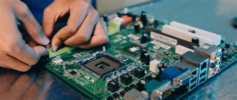
Flying probe test to detect the electrical performance of PCB board
Flying probe test: replace the needle bed with a probe, use multiple motor-driven, fast-moving electrical probes to contact the pins of the device and perform electrical measurements.
During the production process of PCB boards, it is inevitable that short circuits, open circuits and leakage and other electrical defects will occur due to external factors. In addition, PCB circuit boards are constantly evolving towards high density, fine pitch and multi-level. If the bad boards are not screened out in time and allowed to flow into the process, it will inevitably cause more cost waste. Therefore, in addition to improving process control, improving testing technology can also provide PCB board manufacturers with solutions to reduce scrap rates and improve product yields.
The methods of electrical testing include: dedicated, universal grid, flying probe, non-contact electron beam (E-Beam), conductive cloth (glue), capacitance (Capacity) and brush test (ATG-SCANMAN). Among them, there are three commonly used equipment, namely dedicated tester (PCB automatic universal tester), high-quality universal tester and flying probe tester.
What is the difference between flying probe test and test stand? What are their respective advantages?
Flying probe test: It uses 4 probes to perform high-voltage insulation and low-resistance continuity tests on circuit boards (testing the open circuit and short circuit of the circuit) without making test fixtures. It is very convenient to test by directly installing the PCB board and running the test program, saving test costs, reducing the time of making test stands, and improving the efficiency of shipment. It is suitable for testing small batches and samples.
The test stand is a special test fixture made for the continuity test of mass-produced PCB boards.
The production cost is high, but the test efficiency is good, and there is no charge for return orders.
First of all, in terms of the applicable purpose of the test technology, the flying probe test is currently suitable for electrical testing equipment used in small-scale production and samples. However, if it is used in medium-scale production, the test cost will be greatly increased due to the slow test speed and expensive equipment. The general-purpose and special-purpose types can reach the standard of economies of scale as long as the output reaches a certain amount, regardless of the level of PCB boards they are used for, and only account for about 2~4% of the selling price. This is also the main reason why the general-purpose and special-purpose types are currently the main types of mass production testers.
Working principle of flying probe test
The flying probe tester is an improvement on the traditional needle bed online automatic high-voltage special PCB board tester, which uses probes instead of needle beds.
When working, the unit under test (UUT) is transported to the tester through a belt or other UUT conveying system, and then the probe of the fixed tester contacts the test pad (TESTpad) and the via (via), thereby testing a single component of the unit under test (UUT). The test probe is connected to the driver and sensor through a multiplex transmission system to test the components on the UUT. While one component is being tested, other components on the UUT are electrically shielded by the probe to prevent reading interference.
Flying probe testers can check for shorts, opens, and component values.
A camera is also used on flying probe testers to help find missing components. Cameras are used to check for well-defined component shapes, such as polarized capacitors.
With probe positioning accuracy and repeatability in the 5-15 micron range, flying probe testers can precisely probe the UUT. Flying probe testing solves a number of existing problems seen in PCB assembly: test development cycles that can be as long as 4-6 weeks; the inability to economically test small production runs; and the inability to quickly test prototype assembly.
Flying probe testing is a method of checking the electrical functionality of PCB boards (open and short circuit testing).
A flying probe tester is a system for testing PCBs in a manufacturing environment. Instead of using the traditional bed-of-nails interface found on traditional in-circuit testers, flying probe testing uses four to eight independently controlled probes that move to the component under test. The unit under test (UUT) is transported to the tester by a belt or other UUT transport system. Then fix it, and the probe of the tester contacts the test pad and the via to test the single component of the unit under test (UUT). The test probe is connected to the driver (signal generator, power supply, etc.) and sensor (digital multimeter, frequency counter, etc.) through a multiplexing system to test the components on the UUT. When a component is being tested, other components on the UUT are electrically shielded by the probe to prevent reading interference.
Charge/discharge time method
The charge/discharge time (also called network value, net value) of each network is certain. If there are equal network values, there may be a short circuit between them. It is only necessary to measure the short circuit in the network with equal network values. Its test steps are: first board: full open circuit test → full short circuit test → network value learning; second and subsequent boards: full open circuit test → network value test, and then use the resistance method to test where there is a suspected short circuit. The advantages of this test method are accurate test results and high reliability; the disadvantages are that the first board test time is long, the number of retests is large, and the test efficiency is not high. The most representative one is the SPEEDY machine of MANIA.
Inductance measurement method
The principle of the inductance measurement method is to use one or several large networks (generally ground grids) as antennas, apply signals on them, and other networks will sense a certain inductance. The test machine measures the inductance of each network and compares the inductance values of each network. If the network inductance values are the same, there may be a short circuit, and then a short circuit test is performed. This test method is only suitable for testing boards with ground layers. If the test reliability of double-sided boards (without ground grids) is not high; when there are multiple large-scale networks, because there is more than one probe for applying signals, the number of probes provided for testing is reduced, and the test efficiency is low. The advantage is that the test reliability is high and the number of return tests is low. The most representative ones are ATG’s A2 and A3 machines. To make up for the number of probes, the machine is equipped with 8 pins and 16 pins to improve the test efficiency.
Capacitance measurement method
This method is similar to the charge/discharge time method. According to the law relationship between conductive patterns and capacitance, if a reference plane is set, the distance from the conductive pattern to it is L, and the area of the conductive pattern is A, then C=εA/L. If an open circuit occurs, the area of the conductive pattern decreases, and the corresponding capacitance decreases, indicating an open circuit; if two parts of the conductive pattern are connected together, the capacitance response increases, indicating a short circuit. In the open circuit test, the capacitance values of each end of the same network should be equal. If they are not equal, there is an open circuit, and the capacitance value of each network is recorded as a comparison for the short circuit test. The advantage of this method is high test efficiency, and the disadvantage is that it is completely dependent on capacitance, and capacitance is affected by many factors. The test reliability is lower than the resistance method, especially the measurement error caused by the associated capacitance and secondary capacitance. The test reliability of networks with fewer endpoints (such as single-point networks) is low. Currently, the flying probe testers of HIOKI and NIDEC READ use this test method.
Phase difference method
This method is to add a sine wave signal to the ground layer or electrical layer, and use the line layer to obtain the phase lag angle to obtain the capacitance value or inductance value. The test steps are to test the open circuit of the first board first, then the phase difference of other networks, and finally the short circuit; the second and above boards are tested for open circuit first, then the network phase difference, and the possible short circuit is tested and verified by the resistance method. The advantages of this method are high test efficiency and high reliability; the disadvantage is that it is only suitable for testing boards with more than 4 layers. For example, the resistance method can only be used to test double-sided boards. Currently, companies that use this test method include MicroCraft.
Adaptive test method
The adaptive test method is that each test application process is completed once. According to the specific situation and test specifications of the wrench, the device selects the appropriate test process by itself. For example, if the network value of a network (charging time or capacitance, etc.) is less than the test error of the device, the device will automatically use resistance test and electric field test. This test method is the fastest and has the best test effect. However, I have not yet come into contact with a test machine that uses this test method.
The flying probe tester is an improvement on the traditional needle bed online tester. It can use probes instead of needle beds.
There are 4 heads with high-speed movement and a total of 8 test probes on the X-Y mechanism, and the minimum test gap is 0.2mm. During operation, the unit under test (UUT) is transported to the tester by a belt or other UUT conveying system, and then the probes of the fixed tester contact the test pads and vias to test the individual components of the unit under test (UUT). The test probes are connected to the drivers (signal generators, power supplies, etc.) and sensors (digital multimeters, frequency counters, etc.) through a multiplexing system to test the components on the UUT. While one component is being tested, other components on the UUT are electrically shielded by the probe to prevent reading interference.
The flying probe tester can check short circuits, open circuits and component values. A camera is also used on the flying probe test to help find missing components. The camera is used to check the shape of components with clear directions, such as polarized capacitors. With probe positioning accuracy and repeatability in the range of 5-15 microns, the flying probe tester can precisely detect the UUT