High speed pcb simulation
High speed PCB simulation is the process of using software tools to simulate the behavior of a printed circuit board (PCB) at high frequencies.
This type of simulation is important for designing and testing high-speed digital circuits,
such as those used in modern electronic devices like smartphones, computers, and networking equipment.
High speed PCB simulation involves modeling the electrical properties of the PCB,
including its transmission lines, vias, and other components, and analyzing the behavior of signals as they travel through the board.
The simulation results can be used to optimize the design of the PCB and ensure that it meets the required performance specifications.

There are several types of simulations that can be performed on high-speed PCBs, including:
1. Signal integrity simulation:
This type of simulation models the behavior of high-speed signals on the PCB, including reflections, crosstalk, and attenuation.
It can help identify potential issues such as signal distortion, timing errors, and signal loss.
2. Power integrity simulation:
This type of simulation models the behavior of the power distribution network on the PCB,
including voltage drops, noise, and ripple. It can help identify potential issues such as power supply noise, voltage fluctuations, and ground bounce.
3. Electromagnetic interference (EMI) simulation:
This type of simulation models the behavior of electromagnetic fields on the PCB, including radiation and susceptibility.
It can help identify potential issues such as electromagnetic interference, cross-coupling, and radiated emissions.
Simulation software such as Altium Designer, Cadence Allegro, and Mentor Graphics HyperLynx are commonly used for high-speed PCB simulation.
These tools allow designers to create virtual models of their PCBs, simulate various scenarios,
and analyze the results to optimize the design for performance and reliability.

how to design high speed pcb
Designing a high-speed PCB can be a complex process, but here are some general steps to follow:
1. Determine the requirements:
Before starting the design, it is important to determine the requirements of the PCB,
such as the maximum frequency, signal integrity, power requirements, and form factor.
2. Select components:
Select components that meet the requirements and are suitable for high-speed applications.
This includes high-speed connectors, high-frequency capacitors, and inductors.
3. Layout the PCB:
Place components on the PCB and route the traces to minimize signal loss and interference.
Use ground planes and power planes to provide a low impedance path for signals and reduce noise.
4. Follow best practices:
Follow best practices for high-speed PCB design, such as keeping traces short,
using differential pairs, avoiding sharp corners, and maintaining proper spacing between traces.
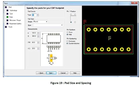
5. Simulate the design:
Use simulation software to simulate the behavior of the PCB at high frequencies.
This can help identify potential issues and optimize the design.
6. Prototype and test:
Build a prototype of the PCB and test it to ensure it meets the requirements.
Make any necessary adjustments and repeat the testing until the design is finalized.
7. Document the design:
Document the design, including schematics, layout files, and bill of materials, for future reference and manufacturing.

high speed pcb design basics
High-speed PCB design refers to the process of designing printed circuit boards that are capable of transmitting high-frequency signals with minimal loss and distortion.
Here are some basic principles to keep in mind when designing high-speed PCBs:
1. Signal Integrity:
High-speed signals are prone to reflection, crosstalk, and noise.
Therefore, it is essential to maintain signal integrity by minimizing the length of the signal traces,
reducing the number of vias, and using controlled impedance routing.
2. Power Integrity:
High-speed signals require a stable power supply.
Therefore, it is important to design the power delivery network (PDN) to minimize voltage drops and noise.
3. Grounding:
Grounding is critical for high-speed PCBs.
A solid ground plane should be used to provide a low impedance path for return currents.
It is also important to minimize the loop area between the signal trace and its return path.
4. Component Placement:
The placement of components on the PCB can have a significant impact on signal integrity.
High-speed components should be placed close to each other to minimize the length of the signal traces.
5. EMI/EMC:
High-speed signals can generate electromagnetic interference (EMI) and electromagnetic compatibility (EMC) issues.
Shielding, filtering, and proper grounding can help mitigate these issues.
6. PCB Stackup:
The PCB stackup should be designed to provide the required impedance for high-speed signals.
A four-layer stackup with a signal layer, a ground plane, and two power planes is commonly used for high-speed PCBs.
7. Design for Manufacturability:
High-speed PCBs can be challenging to manufacture.
Therefore, it is important to design the PCB with manufacturability in mind.
This includes using standard PCB materials, avoiding complex routing, and minimizing the number of vias.