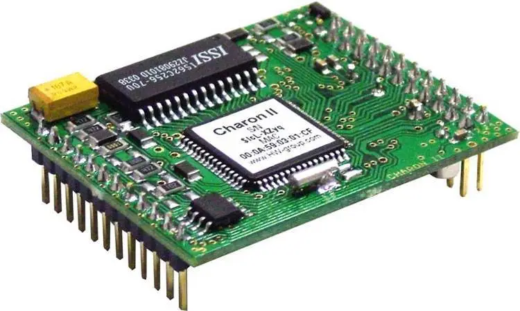
High voltage pcb clearance
Importance Of High Voltage PCB Clearance In Circuit Design
In the realm of circuit design, the importance of high voltage PCB clearance cannot be overstated. As electronic devices become increasingly complex and compact, ensuring adequate clearance on printed circuit boards (PCBs) is crucial for both safety and functionality. High voltage applications, in particular, demand meticulous attention to clearance specifications to prevent electrical failures and ensure the longevity of the device.
To begin with, high voltage PCB clearance refers to the minimum distance required between conductive elements on a PCB to prevent electrical arcing.
This distance is critical in high voltage applications where the potential for arcing is significantly increased due to the higher energy levels involved. Arcing can lead to catastrophic failures, including short circuits, component damage, and even fires. Therefore, maintaining proper clearance is essential to safeguard the integrity of the circuit and the safety of the end-users.
Moreover, the significance of high voltage PCB clearance extends beyond safety concerns.
It also plays a pivotal role in the performance and reliability of electronic devices. Inadequate clearance can result in electromagnetic interference (EMI), which can disrupt the normal operation of the circuit. This interference can lead to erratic behavior, data corruption, and reduced efficiency, ultimately compromising the device’s performance. By adhering to appropriate clearance guidelines, designers can minimize EMI and ensure that the device operates as intended.
Furthermore, the determination of appropriate clearance distances is influenced by several factors, including the operating voltage, environmental conditions, and the materials used in the PCB.
For instance, higher operating voltages necessitate larger clearance distances to prevent arcing. Similarly, environmental factors such as humidity and altitude can affect the dielectric properties of the air, thereby impacting the required clearance. Additionally, the choice of PCB materials, such as the type of substrate and solder mask, can influence the dielectric strength and, consequently, the clearance requirements.
In addition to these considerations, regulatory standards and industry guidelines provide valuable insights into the appropriate clearance distances for high voltage applications.
Organizations such as the International Electrotechnical Commission (IEC) and Underwriters Laboratories (UL) have established standards that outline the minimum clearance requirements based on voltage levels and other parameters. Adhering to these standards not only ensures compliance but also enhances the safety and reliability of the device.
Transitioning to the design phase, it is imperative for engineers to incorporate high voltage PCB clearance considerations early in the design process.
This proactive approach allows for the identification and mitigation of potential issues before they manifest in the final product. Advanced simulation tools and software can aid in visualizing and optimizing clearance distances, enabling designers to make informed decisions and achieve optimal results.
In conclusion, the importance of high voltage PCB clearance in circuit design is multifaceted, encompassing safety, performance, and compliance aspects. By understanding and implementing appropriate clearance guidelines, designers can mitigate the risks associated with high voltage applications and ensure the successful operation of electronic devices. As technology continues to evolve, the emphasis on high voltage PCB clearance will remain a critical component of circuit design, underscoring its enduring relevance in the field of electronics.

Best Practices For Ensuring Adequate PCB Clearance In High Voltage Applications
In the realm of high voltage applications, ensuring adequate printed circuit board (PCB) clearance is paramount to maintaining both functionality and safety. High voltage PCBs are integral to a wide array of industries, from telecommunications to power distribution, and the stakes are high when it comes to their design and implementation. Therefore, understanding and applying best practices for PCB clearance is essential for engineers and designers who aim to optimize performance while minimizing risks.
To begin with, it is crucial to comprehend the concept of PCB clearance, which refers to the minimum distance between conductive elements on a PCB.
This distance is vital in preventing electrical arcing and ensuring that the board can handle the intended voltage without failure. In high voltage applications, the risk of arcing increases significantly, making clearance a critical design consideration. Consequently, adhering to industry standards and guidelines, such as those set by the IPC (Institute for Printed Circuits), is a fundamental step in the design process.
One of the primary factors influencing PCB clearance is the operating environment.
For instance, boards that are exposed to high humidity or dust may require greater clearance to prevent conductive paths from forming across the board’s surface. Additionally, the altitude at which the PCB will operate can affect clearance requirements, as higher altitudes reduce air pressure and increase the likelihood of arcing. Therefore, designers must account for these environmental variables when determining the appropriate clearance for their specific application.
Moreover, the choice of materials plays a significant role in ensuring adequate PCB clearance.
High-quality dielectric materials with superior insulating properties can enhance the board’s ability to withstand high voltages. Selecting materials with a high comparative tracking index (CTI) can further mitigate the risk of electrical tracking, which occurs when a conductive path forms across the surface of an insulating material. By prioritizing materials with robust insulating capabilities, designers can effectively increase the safety margin of their high voltage PCBs.
In addition to material selection, the layout of the PCB is another critical aspect to consider.
Proper component placement and routing can significantly impact the board’s ability to handle high voltages. For example, maintaining ample spacing between high voltage and low voltage components can prevent potential interference and ensure reliable operation. Furthermore, employing techniques such as creepage and clearance analysis during the design phase can help identify potential problem areas and allow for adjustments before manufacturing.
Another best practice involves the use of conformal coatings, which provide an additional layer of protection against environmental factors that could compromise PCB clearance.
These coatings can prevent moisture ingress and reduce the risk of contamination, thereby enhancing the board’s overall reliability. However, it is essential to select a coating that is compatible with the board’s materials and intended operating conditions to maximize its effectiveness.
Finally, rigorous testing and validation are indispensable in ensuring that a high voltage PCB meets clearance requirements.
Subjecting the board to electrical stress tests and environmental simulations can reveal potential weaknesses and allow for corrective measures before deployment. By incorporating thorough testing protocols, designers can ensure that their PCBs not only meet industry standards but also perform reliably in real-world applications.
In conclusion, ensuring adequate PCB clearance in high voltage applications is a multifaceted process that demands careful consideration of environmental factors, material selection, layout design, protective coatings, and comprehensive testing. By adhering to these best practices, engineers and designers can create high voltage PCBs that are both safe and efficient, ultimately contributing to the success and reliability of the systems they support.

Common Mistakes To Avoid In High Voltage PCB Clearance
When designing high voltage printed circuit boards (PCBs), ensuring proper clearance is crucial to maintaining safety and functionality. However, several common mistakes can compromise the integrity of these designs, leading to potential failures or hazards. Understanding and avoiding these pitfalls is essential for engineers and designers working with high voltage applications.
One prevalent mistake is underestimating the required clearance distances.
Clearance refers to the shortest path between two conductive parts through air, and it is vital for preventing electrical arcing. Designers often miscalculate these distances due to a lack of understanding of the voltage levels involved or the environmental conditions the PCB will face. It is essential to adhere to industry standards, such as those outlined by the IPC-2221 guidelines, which provide minimum clearance distances based on voltage levels and environmental factors. Failing to do so can result in insufficient spacing, increasing the risk of arcing and potential damage to the PCB.
Another common error is neglecting to account for the effects of environmental factors on clearance requirements.
Factors such as humidity, altitude, and pollution can significantly impact the necessary clearance distances. For instance, high humidity can reduce the dielectric strength of air, necessitating greater clearance to prevent arcing. Similarly, at higher altitudes, the reduced air pressure can lower the breakdown voltage, requiring adjustments in clearance. Designers must consider these environmental conditions during the design phase to ensure the PCB operates safely under all expected conditions.
In addition to environmental considerations, material selection plays a critical role in determining appropriate clearance.
Using materials with inadequate dielectric properties can lead to breakdowns and failures. It is crucial to select materials with high dielectric strength and thermal stability to withstand the operational stresses of high voltage applications. Furthermore, designers should be aware of the potential for material degradation over time, which can affect clearance requirements. Regular testing and validation of materials can help mitigate this risk.
Moreover, improper layout and routing of traces can also lead to clearance issues.
Designers sometimes overlook the importance of maintaining adequate spacing between high voltage traces and other components. This oversight can result in unintended coupling or crosstalk, which may compromise the performance and safety of the PCB. Employing careful layout strategies, such as increasing the distance between high voltage and low voltage traces, can help prevent these issues. Additionally, using techniques like guard traces or ground planes can further enhance isolation and reduce the risk of electrical interference.
Furthermore, inadequate consideration of manufacturing tolerances can lead to clearance problems.
Variations in the manufacturing process can result in deviations from the intended design, potentially reducing the actual clearance on the finished PCB. Designers should work closely with manufacturers to understand their capabilities and limitations, ensuring that the design accounts for any potential variations. Implementing design for manufacturability (DFM) practices can help mitigate these risks by aligning the design with the manufacturing process.
In conclusion, avoiding common mistakes in high voltage PCB clearance is essential for ensuring the safety and reliability of electronic systems.
By accurately calculating clearance distances, considering environmental factors, selecting appropriate materials, optimizing layout and routing, and accounting for manufacturing tolerances, designers can create robust and reliable high voltage PCBs. Adhering to these best practices not only enhances the performance of the PCB but also minimizes the risk of electrical failures and hazards, ultimately contributing to the overall success of high voltage applications.

Innovations In High Voltage PCB Clearance Techniques And Materials
In the realm of electronics, the demand for high voltage printed circuit boards (PCBs) has been steadily increasing, driven by advancements in technology and the need for more efficient power management systems. As these high voltage applications become more prevalent, ensuring adequate clearance on PCBs is crucial to prevent electrical arcing and ensure safety and reliability. Innovations in high voltage PCB clearance techniques and materials have thus become a focal point for engineers and designers seeking to optimize performance while maintaining safety standards.
One of the primary considerations in high voltage PCB design is the clearance, which refers to the physical distance between conductive elements on the board.
This distance is critical in preventing electrical arcing, which can lead to circuit failure or even catastrophic damage. Traditionally, designers have relied on established standards and guidelines to determine the appropriate clearance distances. However, as technology evolves, so too do the methods and materials used to achieve these clearances.
Recent innovations have introduced advanced materials that enhance the dielectric properties of PCBs, allowing for reduced clearance distances without compromising safety.
These materials, often composites or specialized coatings, provide superior insulation and can withstand higher voltages. By utilizing such materials, designers can create more compact and efficient PCB layouts, which is particularly beneficial in applications where space is at a premium.
In addition to material advancements, new techniques in PCB manufacturing have also contributed to improved high voltage clearance.
For instance, precision laser cutting and etching technologies enable more accurate and consistent creation of clearance gaps. These techniques allow for tighter tolerances and more intricate designs, which can be crucial in high-density applications. Moreover, the use of computer-aided design (CAD) software has revolutionized the way engineers approach PCB layout, providing tools to simulate and optimize clearance distances before physical production begins.
Furthermore, the integration of three-dimensional (3D) printing technology in PCB manufacturing has opened new avenues for innovation.
3D printing allows for the creation of complex geometries and structures that were previously difficult or impossible to achieve with traditional methods. This capability can be leveraged to design PCBs with unique clearance solutions, such as embedded channels or barriers that enhance electrical isolation.
While these innovations offer significant benefits, they also present new challenges.
The introduction of novel materials and techniques requires rigorous testing and validation to ensure they meet industry standards and regulatory requirements. Engineers must carefully evaluate the thermal and mechanical properties of new materials, as well as their long-term reliability under high voltage conditions. Additionally, the adoption of advanced manufacturing techniques necessitates investment in new equipment and training, which can be a barrier for some organizations.
In conclusion, the field of high voltage PCB clearance is undergoing a transformation driven by innovations in materials and manufacturing techniques. These advancements offer the potential for more efficient and compact designs, which are essential in meeting the growing demands of modern electronic applications. However, they also require careful consideration and validation to ensure safety and reliability are not compromised. As the industry continues to evolve, ongoing research and development will be key to unlocking the full potential of these innovations, paving the way for the next generation of high voltage electronic systems.

