How should we adjust the PCB after it is proofed?
Whether it is a board made by someone else or a PCB board designed and made by ourselves, the first thing to do when we get it is to check the integrity of the board, such as tinning, cracks, short circuits, open circuits and drilling. If the function of the board is more rigorous, you can also check the resistance value between the power supply and the ground wire.
Generally, the components will be installed on the board made by yourself after the tinning is completed, while if it is made by someone else, it is just an empty shell of a tinned PCB board with holes, and you need to install the components yourself when you get it.
Some people have a lot of information about the PCB board they designed, so they like to install all the components at once and then test it. In fact, it is recommended to do it bit by bit.
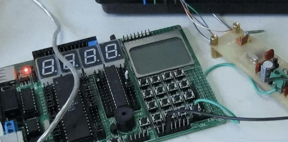
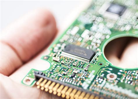
PCB circuit board in debugging
The debugging of the new PCB board can start from the power supply. The safest way is to put on a fuse and then connect the power supply (it is best to use a stabilized power supply just in case).
Use a stabilized power supply to set the overcurrent protection current, and then slowly increase the stabilized power supply voltage. This process requires monitoring the input current, input voltage and output voltage of the board.
When the voltage is adjusted upward, there is no overcurrent protection and the output voltage is normal, which means that there is no problem with the power supply part of the board. If it exceeds the normal output voltage or overcurrent protection, then the cause of the fault must be checked.
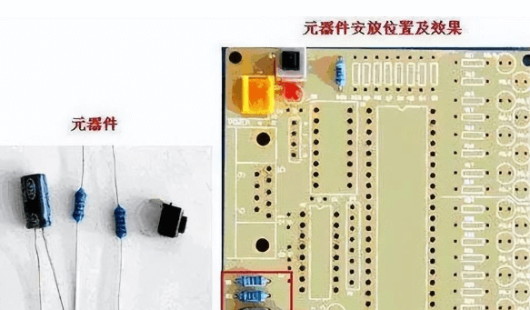
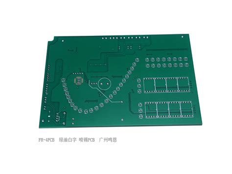
Circuit board component installation
Install the modules gradually during the debugging process. Follow the above steps for testing each time one or several modules are installed. This helps to avoid some more hidden errors in the initial design or installation errors, which may cause overcurrent to burn out components.
If a fault occurs during the installation process, the following methods are generally used for troubleshooting:
Troubleshooting method 1: voltage measurement method

Measurement voltage method
When overcurrent protection occurs, do not rush to disassemble the components. First, confirm the voltage of the power pins of each chip to see if it is within the normal range. Then check the reference voltage, working voltage, etc. in turn.
For example: when the silicon triode is turned on, the voltage of the BE junction will be around 0.7V, and the CE junction is generally 0.3V or less.
When the BE junction voltage is higher than 0.7V during the test (special transistors such as Darlington are excluded here), it is possible that the BE junction is open. In this way, the voltage at each point can be checked to eliminate the fault.
Troubleshooting method 2: signal injection method
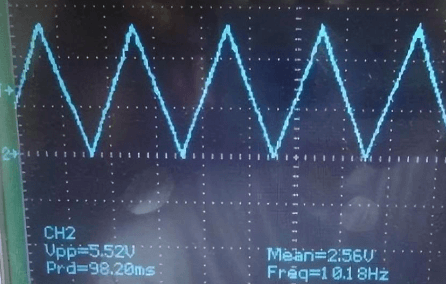
Signal injection method
The signal injection method is more troublesome than measuring voltage. After the signal source is transmitted to the input end, we need to measure the waveform of each point in turn and find the fault point from the waveform.
Of course, you can also use tweezers to detect the input end. The method is to touch the input end with tweezers and then observe the response of the input end. Generally, this method is used in audio and video amplifier circuits (Note: Do not use this method for hot floor circuits and high voltage circuits, as it is easy to cause electric shock accidents).
This method detects that the previous level is normal, and the next level has a response, so the fault is not in the next level, but in the previous level.
Troubleshooting method 3: Others
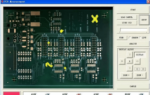
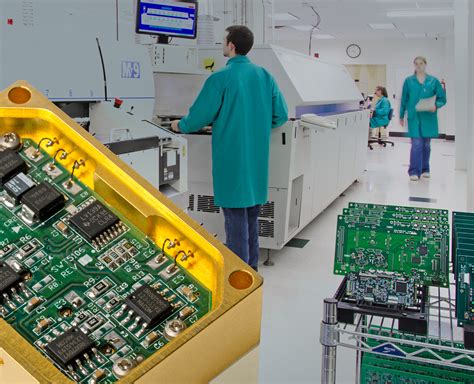
PCB circuit board appearance inspection machine
The above two methods are relatively simple and direct methods. In addition, such as the commonly said look, smell, listen, touch, etc., it requires some experienced engineers to detect the problem.
Generally speaking, “looking” does not mean checking the status of the testing instrument, but checking whether the appearance of the components is intact; “smelling” mainly means smelling whether the smell of the components is abnormal, such as burning smell, electrolyte smell, etc. Generally, components will emit an unpleasant burning smell when they are damaged.
“Listening” mainly means listening to whether the sound of the board is normal under working conditions; “touching” does not mean touching whether the components are loose, but using your hands to feel whether the temperature of the components is normal. For example, under working conditions, the components that should be cold are hot, while the components that should be hot are abnormally cold. Do not pinch directly with your hands during the touching process to prevent your hands from being burned by excessive temperature.