How to Change Net Colors in the PCB Interface of Altium Designer
Introduction to Net Coloring in PCB Design
In modern PCB design, effectively managing and visualizing different nets (electrical connections) is crucial for efficient layout and debugging. Altium Designer, one of the most popular PCB design tools in the industry, provides comprehensive net coloring capabilities that allow designers to visually distinguish between various nets in the PCB interface. This functionality becomes particularly valuable when working with complex designs containing hundreds or thousands of nets.
Changing net colors serves multiple purposes in the PCB design workflow. First, it enhances visual clarity, making it easier to track specific nets throughout the board. Second, it helps in identifying critical nets that may require special routing considerations (such as high-speed or high-current nets). Third, colored nets can significantly improve collaboration when multiple engineers are working on the same design.
This article will provide a detailed, step-by-step guide on how to change net colors in Altium Designer’s PCB interface, covering various methods and scenarios you might encounter during the PCB design process.
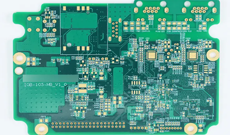
Accessing Net Color Settings in Altium Designer
To begin changing net colors in Altium Designer, you first need to access the appropriate interface for net management:
- Open your PCB project in Altium Designer and ensure the PCB document is active
- Navigate to the “View” menu in the top toolbar
- Select “Workspace Panels” from the dropdown
- Choose “PCB” and then “PCB” again to open the PCB panel
- In the PCB panel, select “Nets” from the dropdown menu at the top
Alternatively, you can use the shortcut Ctrl+H to quickly access the Nets view in the PCB panel. This panel displays all the nets in your current PCB design, organized hierarchically according to your schematic structure.
Once you have the Nets view open, you’ll see several columns displaying information about each net, including its name, connection count, and current color assignment (if any). The color column may appear blank initially for most nets, as they typically default to the layer color where they’re routed.
Assigning Colors to Individual Nets
The most straightforward method to change a net’s color is to assign a color directly to that specific net:
- Locate the net you want to color in the Nets panel
- Right-click on the net name to open the context menu
- Select “Change Net Color” from the menu options
- A color picker dialog will appear – choose your desired color
- Click “OK” to apply the color
After assigning a color, you’ll immediately see the change reflected in the PCB editor. All objects associated with that net (tracks, vias, pads) will now display in the chosen color, overriding the default layer colors.
To make the colored nets more visible, you might want to:
- Enable color override by toggling the “Override All Nets Colors” button in the Nets panel (the multicolored square icon)
- Adjust the display intensity using the “Mask and Dim Settings” (accessible via the “View” > “Mask and Dim Settings” menu)
Remember that assigning colors to individual nets works best when you only need to highlight a small number of critical nets. For more complex coloring schemes, other methods might be more efficient.

Creating and Applying Net Color Schemes
For designs requiring more sophisticated coloring approaches, Altium Designer offers Net Color Schemes. These allow you to define and save complete sets of net color assignments that can be easily applied, modified, and reused across different projects or design stages.
To create a Net Color Scheme:
- Open the “Design” menu in the top toolbar
- Select “Netlist” and then “Manage Net Color Schemes”
- In the dialog that appears, click “Add” to create a new scheme
- Name your scheme appropriately (e.g., “Power Nets” or “Signal Groups”)
- Select nets from the list and assign colors as needed
- Click “OK” to save the scheme
Once created, you can apply a saved color scheme at any time:
- Access the “Manage Net Color Schemes” dialog as described above
- Select the desired scheme from the list
- Click “Apply” to implement the color assignments
Net Color Schemes are particularly useful for:
- Maintaining consistent coloring across project revisions
- Quickly switching between different coloring perspectives (e.g., functional groups vs. voltage levels)
- Sharing color standards among team members
Advanced Net Coloring Techniques
Beyond basic color assignment, Altium Designer provides several advanced net coloring features that can enhance your PCB design workflow:
1. Color by Net Class:
- First, define net classes in the PCB panel (Design > Classes)
- Right-click a net class and select “Change Net Color”
- All nets in the class will inherit the assigned color
2. Differential Pair Coloring:
- Differential pairs can be colored as a unit for easy identification
- Access through the Differential Pairs Editor (Design > Differential Pairs)
- Assign colors to the positive and negative nets simultaneously
3. Layer-based Net Coloring:
- While not strictly net-based, you can set layer colors to emphasize nets routed on specific layers
- Configure in View Configuration panel (shortcut L)
4. Temporary Net Highlighting:
- Use the “Highlight Nets” feature (Tools > Highlight Nets) for temporary emphasis
- Particularly useful during routing or debugging sessions
5. Net Color Inheritance:
- Colors can be inherited from schematic directives if properly configured
- Ensures consistency between schematic and PCB views
Managing and Clearing Net Colors
As your design evolves, you may need to modify or remove net color assignments. Altium provides several methods for managing existing colors:
To clear a single net’s color:
- Right-click the net in the Nets panel
- Select “Clear Net Color”
To clear all net colors at once:
- Click the “Clear All Net Colors” button in the Nets panel (the eraser icon)
- Confirm the action in the dialog that appears
To temporarily disable all net colors:
- Toggle off the “Override All Nets Colors” button in the Nets panel
- This reverts display to standard layer colors without deleting color assignments
To export/import color schemes:
- Use the “Manage Net Color Schemes” dialog
- Select a scheme and use the “Export” or “Import” buttons
- Useful for sharing color standards across teams
Best Practices for Net Coloring in PCB Design
Effective use of net coloring can significantly improve your design efficiency, but it’s important to follow some best practices:
- Develop a consistent color coding system – Use the same colors for similar net types across projects (e.g., red for power, blue for ground, green for critical signals)
- Limit the number of colored nets – Overuse of colors can create visual clutter. Focus on highlighting only the most important nets.
- Use color to reflect function or priority – For example, highlight high-speed nets in one color scheme, power delivery in another.
- Combine colors with other visual aids – Use width, spacing, and layer awareness in conjunction with color for maximum clarity.
- Document your color scheme – Include a legend in your design documentation explaining what each color represents.
- Consider colorblind accessibility – Choose colors that remain distinguishable for colorblind team members (tools like Color Oracle can help test this).
- Use color schemes for different phases – You might have one scheme for initial layout, another for DRC checking, and another for manufacturing review.
Troubleshooting Common Net Color Issues
Even with Altium’s intuitive interface, you might encounter some challenges when working with net colors. Here are solutions to common issues:
Problem: Assigned colors aren’t visible
- Solution: Ensure “Override All Nets Colors” is enabled in the Nets panel
- Check that the objects aren’t being hidden by other display settings
Problem: Colors reset after design changes
- Solution: Net colors are persistent with the PCB file, but schematic changes that affect net names might require reapplication
- Consider using Net Classes for more stable color assignments
Problem: Performance slows with many colored nets
- Solution: Reduce the number of colored nets or use simpler color schemes
- Close unnecessary panels to free up system resources
Problem: Colors don’t match between schematic and PCB
- Solution: Use the “Update Schematics” feature to synchronize net information
- Consider using Schematic Directives to push color information to the PCB
Conclusion
Mastering net color management in Altium Designer’s PCB interface is an essential skill for efficient PCB design. By following the methods outlined in this article – from basic color assignment to advanced scheme management – you can significantly enhance your design workflow, improve collaboration, and reduce errors. Remember that effective use of color is as much an art as it is a technical skill; develop a system that works for your specific needs and stick with it consistently across projects.
As you become more comfortable with net coloring, experiment with different approaches to find what works best for your design style and team requirements. The visual clarity provided by thoughtful net coloring can make the difference between a good PCB design and a great one.

