How to Choose the Right PCB Manufacturing Materials Based on Your Requirements
Introduction
Printed Circuit Boards (PCBs) form the foundation of nearly all modern electronic devices, from smartphones to industrial equipment. The selection of appropriate PCB materials is one of the most critical decisions in the design and manufacturing process, as it directly impacts the board’s performance, reliability, durability, and cost. With hundreds of material options available—each with unique properties—engineers must carefully evaluate their specific requirements to make optimal choices.
This comprehensive guide explores the key factors to consider when selecting PCB manufacturing materials, examines the most common material types and their characteristics, and provides practical recommendations for various applications.
Understanding PCB Material Composition
Before diving into selection criteria, it’s essential to understand the basic composition of PCB materials. Most PCB substrates consist of:
- Dielectric Layer (Substrate): The insulating base material that provides mechanical support
- Conductive Layer: Typically copper foil for electrical pathways
- Protective Layers: Solder mask and silkscreen for protection and labeling
The dielectric substrate material is typically the primary focus of material selection, as it determines most of the board’s fundamental characteristics.
Key Factors in PCB Material Selection
1. Electrical Requirements
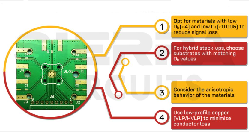
Dielectric Constant (Dk): This measures how easily the material can store electrical energy. Lower Dk values (typically 2-5) are better for high-frequency applications as they reduce signal propagation delays and crosstalk.
Dissipation Factor (Df): Also called loss tangent, this indicates signal loss through the dielectric material. High-frequency applications require low Df values (0.001-0.005) to minimize energy loss.
Electrical Strength: The maximum electric field the material can withstand without breakdown, important for high-voltage applications.
2. Thermal Properties
Glass Transition Temperature (Tg): The temperature at which the substrate changes from rigid to soft. Higher Tg materials (170°C+) are needed for lead-free soldering and high-temperature environments.
Coefficient of Thermal Expansion (CTE): Measures how much the material expands when heated. Matching CTE between layers prevents delamination during thermal cycling.
Thermal Conductivity: Important for heat dissipation in high-power applications. Some specialized materials offer enhanced thermal conductivity.
3. Mechanical Requirements
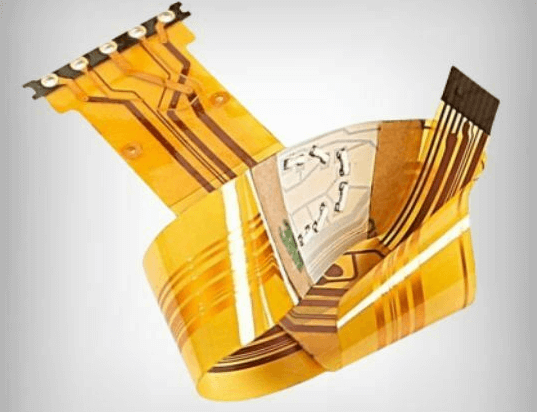
Flexibility: Rigid, flexible, or rigid-flex requirements dictate material choices. Polyimide is common for flexible circuits.
Strength & Durability: Mechanical stress requirements influence material thickness and reinforcement choices.
Weight: Aerospace and portable devices often need lightweight materials.
4. Environmental Considerations
Moisture Absorption: Materials with low absorption rates (under 0.2%) perform better in humid environments.
Chemical Resistance: Resistance to solvents, acids, and other chemicals may be required for certain applications.
Flame Retardancy: Most applications require UL94 V-0 or similar flame-retardant ratings.
5. Manufacturing Considerations
Drillability: Some high-frequency materials are more difficult to drill, increasing fabrication costs.
Dimensional Stability: Materials that maintain size during processing enable finer features and higher yields.
Availability: Some specialized materials have long lead times or limited suppliers.
6. Cost Constraints
Material costs can vary significantly—from standard FR-4 at a few dollars per square foot to specialized high-frequency materials costing hundreds. Balancing performance needs with budget is crucial.
Common PCB Material Types and Their Applications
1. FR-4 (Flame Retardant 4)
Composition: Woven fiberglass cloth with epoxy resin binder
Characteristics:
- Dk: ~4.3-4.8 at 1 MHz
- Tg: 130-180°C (standard to high-Tg versions)
- Cost-effective
- Good mechanical properties
- Moderate electrical performance
Applications: Consumer electronics, industrial controls, automotive electronics, and other general-purpose applications where high-frequency performance isn’t critical.
Variations: High-Tg FR-4 for lead-free assembly, halogen-free versions for environmental compliance.
2. High-Frequency/Low-Loss Materials
Examples: Rogers RO4000 series, Taconic TLY, Isola Astra
Characteristics:
- Dk: 2.2-3.5 (stable over frequency)
- Df: 0.001-0.003
- Excellent signal integrity at high frequencies
- Higher cost than FR-4
Applications: RF/microwave circuits, 5G infrastructure, radar systems, high-speed digital (10+ Gbps).
3. Polyimide
Characteristics:
- High Tg (~250°C+)
- Excellent thermal and chemical resistance
- Good flexibility
- Higher cost than FR-4
Applications: Flexible circuits, aerospace/military, high-temperature environments.
4. PTFE-Based Materials
Examples: Rogers RT/duroid, Taconic RF-35
Characteristics:
- Ultra-low Df (as low as 0.0009)
- Dk: 2.0-2.2
- Excellent high-frequency performance
- Difficult to process
- High cost
Applications: Millimeter-wave applications, satellite communications, advanced radar.
5. Metal-Clad Substrates
Examples: Aluminum, copper base
Characteristics:
- Excellent thermal conductivity
- Electrical isolation through dielectric layer
- Enhanced mechanical strength
Applications: High-power LEDs, power electronics, automotive applications.
6. Ceramic-Based Substrates
Examples: Alumina (Al2O3), Aluminum Nitride (AlN)
Characteristics:
- Excellent thermal conductivity
- High temperature resistance
- Brittle nature
- High cost
Applications: High-power RF, aerospace, specialized industrial.
Selection Guidelines by Application Type
1. Consumer Electronics
Recommendations: Standard or high-Tg FR-4, halogen-free versions for environmental compliance
Considerations: Cost sensitivity, moderate performance requirements, high-volume manufacturability
2. Automotive Electronics
Recommendations: High-Tg FR-4, polyimide for flexible sections, metal-clad for power electronics
Considerations: Temperature cycling resistance, vibration resistance, long-term reliability
3. High-Speed Digital
Recommendations: Low-loss FR-4 variants or mid-range high-frequency materials (Dk 3.5-4.0, Df <0.010)
Considerations: Signal integrity, controlled impedance, dielectric consistency
4. RF/Microwave
Recommendations: PTFE or hydrocarbon ceramic materials (Rogers, Taconic)
Considerations: Stable Dk across frequency bands, minimal loss, often requiring specialized fabrication
5. Aerospace/Military
Recommendations: Polyimide, high-performance PTFE composites, ceramic
Considerations: Extreme temperature ranges, radiation resistance, long-term reliability
6. Medical Electronics
Recommendations: High-reliability FR-4, polyimide for implants
Considerations: Biocompatibility (for implants), sterilization compatibility, long service life
Advanced Considerations for Special Applications
1. High-Density Interconnect (HDI) PCBs
Material requirements:
- Excellent dimensional stability for microvias
- Smooth copper surfaces for fine features
- Low-profile copper foils
2. High-Power Applications
Consider:
- Thermal conductivity needs
- CTE matching to components
- Copper thickness options
3. Mixed-Signal Designs
Strategy:
- Possible use of hybrid constructions
- Careful Dk control for impedance matching
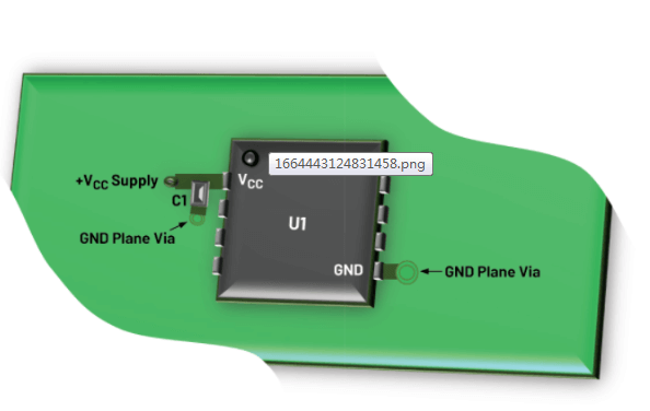
- Ground plane considerations
The Material Selection Process: A Step-by-Step Approach
- Define Application Requirements
- Electrical: Frequency, signal integrity needs
- Thermal: Operating temperatures, power dissipation
- Mechanical: Flexibility, vibration, shock
- Environmental: Humidity, chemicals, radiation
- Regulatory: Safety, flammability standards
- Establish Priority Parameters
- Rank must-have vs. nice-to-have characteristics
- Identify any absolute constraints (e.g., UL certification)
- Screen Available Materials
- Eliminate options that don’t meet critical requirements
- Consider availability and lead times
- Evaluate Cost vs. Performance
- Compare short-term and long-term costs
- Consider manufacturing yield impacts
- Prototype and Test
- Verify performance under actual conditions
- Assess manufacturability
- Finalize Selection
- Document material specifications
- Establish quality acceptance criteria
Common Material Selection Mistakes to Avoid
- Over-specifying Requirements
- Using aerospace-grade materials for consumer products
- Unnecessarily driving up costs
- Underestimating Thermal Requirements
- Ignoring reflow temperature needs
- Neglecting long-term thermal cycling effects
- Ignoring Manufacturing Considerations
- Selecting materials that are difficult to process
- Not accounting for material-specific design rules
- Overlooking Long-Term Reliability
- Focusing only on initial performance
- Neglecting aging characteristics
- Disregarding Supply Chain Factors
- Choosing materials with single-source suppliers
- Not considering lead time impacts
Future Trends in PCB Materials
- Low-Loss Materials for 5G/6G
- Developing substrates with ultra-low Df at mmWave frequencies
- Sustainable Materials
- Bio-based resins
- Improved recyclability
- Embedded Component Substrates
- Materials compatible with embedded actives/passives
- Advanced Thermal Management
- Nanostructured dielectric materials
- Improved thermally conductive but electrically insulating materials
Conclusion
Selecting the optimal PCB manufacturing materials requires careful analysis of electrical, thermal, mechanical, environmental, and cost requirements. While FR-4 serves adequately for most general applications, specialized needs demand more advanced materials with specific characteristics. By systematically evaluating requirements against material properties, engineers can make informed decisions that balance performance, reliability, and cost.
The PCB material landscape continues to evolve, with new formulations addressing emerging challenges in high-speed, high-frequency, and high-reliability applications. Staying informed about these developments enables designers to leverage the most appropriate materials for their specific needs, ultimately resulting in better-performing, more reliable electronic products.
Remember that material selection is just one part of the PCB design and manufacturing process. Close collaboration with your PCB manufacturer and material suppliers can provide valuable insights and help identify optimal solutions for your particular application. Many manufacturers offer material selection guides and application engineering support to assist with these critical decisions.