How to control the precision of PCB board milling
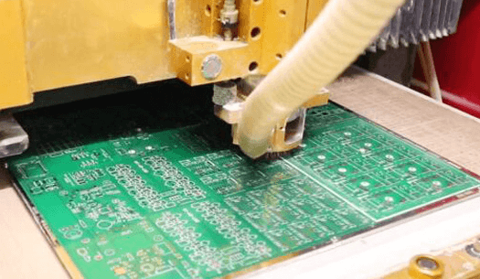
The milling technology of CNC milling machines for circuit boards includes the selection of cutting direction, compensation method, positioning method, frame structure, and cutting point, which are all important aspects to ensure the precision of milling. The following are the precision control skills and methods of PCB board milling summarized by Jieduobang PCB.
Cutting direction and compensation method:
When the milling cutter cuts into the plate, one cut surface always faces the cutting edge of the milling cutter, and the other side always faces the cutting edge of the milling cutter. In the former, the machined surface is smooth and has high dimensional accuracy. The spindle always rotates clockwise. Therefore, whether it is a CNC milling machine with a fixed spindle and a fixed table or a fixed spindle, when milling the outer contour of the printed circuit board, the tool should be moved in the counterclockwise direction.
This is usually called reverse milling. When milling the frame or slot inside the circuit board, the forward milling method is used. Milling compensation is when the machine tool automatically sets the set value to let the milling cutter automatically offset the center of the milling line by half of the set milling cutter diameter, that is, the radius distance, so that the milling shape is consistent with the program setting. At the same time, if the machine tool has the function of compensation, it is necessary to pay attention to the direction of compensation and the command of the program. If the compensation command is used incorrectly, the shape of the circuit board will be more or less equivalent to the length and width of the milling cutter diameter.
Positioning method and cutting point:
Positioning methods can be divided into two types; one is internal positioning and the other is external positioning. Positioning is also very important for process developers. Generally, the positioning plan should be determined in the early stage of circuit board production.
Internal positioning is a common method. The so-called internal positioning is to select the mounting holes, plug-in holes or other non-metallized holes in the printed circuit board as positioning holes. The relative position of the holes should be on the diagonal line and the largest diameter holes should be selected as much as possible. Metallized holes cannot be used. Because the difference in the thickness of the coating in the hole will affect the consistency of the positioning hole you choose, and it is easy to cause damage to the coating in the hole and the edge of the hole surface when taking the board. Under the condition of ensuring the positioning of the printed circuit board, the fewer the number of pins, the better.
Generally, two pins are used for small boards and three pins are used for large boards. Its advantages are accurate positioning, small deformation of the board shape, high precision, good shape, and fast milling speed. Its disadvantages are that there are many types of hole diameters in the board, and pins of various diameters need to be prepared. If there are no available positioning holes in the board, it is necessary to discuss with the customer to add positioning holes in the board during the preliminary production, which is more cumbersome. At the same time, the management of different milling templates for each type of board is more troublesome and expensive.
External positioning is another positioning method, which uses positioning holes on the outside of the board as the positioning holes for milling boards. Its advantage is that it is easy to manage. If the preliminary production is well regulated, there are generally about fifteen types of milling templates. Due to the use of external positioning, the board cannot be milled off at one time, otherwise the circuit board is very easy to damage, especially the board, because the milling cutter and dust collection device will bring the board out, causing damage to the circuit board and breaking of the milling cutter.
The method of segmented milling and leaving the joint point is adopted. The board is milled first. When the milling is completed, the program is paused and the board is fixed with tape. The second section of the program is executed, and a 3mm to 4mm drill is used to drill out the joint point. Its advantages are that there are few templates, low cost and easy management. All circuit boards without mounting holes and positioning holes can be milled. It is easy to manage for small process personnel, especially CAM and other early production personnel. The production can be simplified, and the utilization rate of the substrate can be optimized. The disadvantage is that due to the use of drill bits, at least 2-3 raised points are left on the appearance of the circuit board, which is not beautiful and may not meet customer requirements. The milling time is long and the labor intensity of workers is slightly high.
Frame and cutting point:
The production of the frame belongs to the preliminary production of the circuit board. The frame design not only affects the uniformity of electroplating, but also affects the milling board. If the design is not good, the frame is easy to deform or some small pieces of waste will be produced when milling the board. The waste will block the vacuum tube or break the high-speed rotating milling cutter. The deformation of the frame, especially when the milling board is positioned externally, will cause the finished board to deform. In addition, the selection of the cutting point and the processing sequence can keep the frame at the maximum strength and the fastest speed. If the selection is not good, the frame is easy to deform and the printed board will be scrapped.
Milling process parameters:
Use a carbide milling cutter to mill the shape of the printed board. The cutting speed of the milling cutter is generally 180-270m/min. The calculation formula is as follows (for reference only):
S=pdn/1000 (m/min)
Where: p: PI (3.1415927)
d: milling cutter diameter, mm
n; milling cutter speed, r/min