How to Improve Thermal Management Through PCB Design
Introduction
Thermal management is a critical aspect of printed circuit board (PCB) design, especially as electronic devices become more compact and powerful. Excessive heat can degrade performance, reduce component lifespan, and even lead to catastrophic failure. Effective PCB design plays a vital role in dissipating heat efficiently. This article explores various techniques to enhance thermal management through optimized PCB layout, material selection, and advanced cooling strategies.
1. Understanding Heat Generation in PCBs
Before addressing thermal management, it’s essential to understand how heat is generated in PCBs:
- Resistive Losses: Current flowing through traces and components (e.g., resistors, ICs) generates heat due to electrical resistance.
- Switching Losses: High-frequency components like CPUs and power MOSFETs generate heat during rapid switching.
- Poor Thermal Conductivity: Some PCB materials have low thermal conductivity, trapping heat near components.
By identifying heat sources, designers can implement targeted cooling strategies.
2. PCB Material Selection for Better Heat Dissipation
2.1 High-Thermal-Conductivity Substrates
Traditional FR-4 has low thermal conductivity (~0.3 W/mK). Alternatives include:
- Metal-Core PCBs (MCPCBs): Use aluminum or copper cores (5-400 W/mK) for better heat spreading.
- Ceramic Substrates (AlN, Al₂O₃): Offer excellent thermal performance (24-170 W/mK) for high-power applications.
- Thermally Conductive Dielectrics: Some laminates incorporate fillers (e.g., boron nitride) to improve heat transfer.
2.2 Copper Thickness and Planes
- Thicker copper layers (2 oz vs. 1 oz) reduce resistive losses and improve heat spreading.
- Large copper planes act as heat sinks, distributing heat away from hotspots.
3. Optimizing PCB Layout for Thermal Management
3.1 Component Placement
- Separate Heat-Sensitive Components: Keep temperature-sensitive parts (e.g., sensors) away from high-power devices.
- Distribute High-Power Components: Avoid clustering heat-generating components to prevent localized overheating.
- Elevate Heat Sources: Place hot components near board edges or where airflow is strongest.
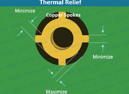
3.2 Thermal Vias and Heat Sinking
- Thermal Vias: Placing vias under hot components (e.g., QFN packages) helps transfer heat to inner layers or backside copper.
- Use arrays of small, filled vias for better thermal conductivity.
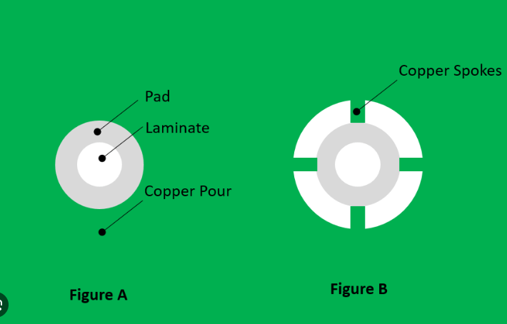
- Copper Pours and Heat Spreaders: Connect thermal vias to large copper areas or external heat sinks.
3.3 Trace Design for Reduced Heating
- Wider Traces: Reduce resistance and Joule heating in high-current paths.
- Avoid Sharp Corners: 45° or curved traces minimize current crowding and heat buildup.
- Differential Pair Routing: Ensures balanced current distribution, reducing localized heating.
4. Advanced Cooling Techniques
4.1 Embedded Cooling Solutions
- Embedded Heat Pipes: Transfer heat efficiently from hotspots to cooler areas.
- Liquid Cooling Channels: Microfluidic channels in multilayer PCBs circulate coolant for extreme cooling needs.
4.2 External Heat Sinks and Fans
- Attached Heat Sinks: Use thermally conductive adhesives or clips to mount heat sinks on high-power components.
- Forced Air Cooling: Strategically placed fans enhance convection cooling, especially in enclosed systems.
4.3 Phase-Change Materials (PCMs)
PCMs absorb heat by changing state (e.g., melting), providing temporary thermal buffering in high-power bursts.
5. Simulation and Testing for Thermal Optimization
5.1 Thermal Simulation Tools
- Finite Element Analysis (FEA): Predicts temperature distribution and identifies hotspots before fabrication.
- Computational Fluid Dynamics (CFD): Models airflow and cooling efficiency in enclosures.
5.2 Infrared Thermography and Testing
- Use IR cameras to validate thermal performance post-production.
- Monitor real-world operating temperatures to refine designs iteratively.
6. Industry Applications
- Consumer Electronics: Smartphones and laptops use thermal vias and graphite sheets for heat spreading.
- Automotive: High-current PCBs in EVs rely on MCPCBs and liquid cooling.
- Aerospace: Ruggedized designs employ ceramic substrates and advanced cooling for reliability.
Conclusion
Effective thermal management in PCB design requires a multi-faceted approach, combining material selection, intelligent layout, and advanced cooling techniques. By leveraging high-thermal-conductivity substrates, optimizing component placement, and utilizing thermal vias, designers can significantly improve heat dissipation. Simulation and testing further ensure reliability in real-world conditions. As electronics continue to push power and size limits, innovative PCB thermal solutions will remain essential for performance and longevity.