How to Maintain PCB Power Integrity: A Comprehensive Guide
Introduction
Power integrity (PI) is a critical aspect of printed circuit board (PCB) design, ensuring that the power delivered to all components remains stable and within acceptable noise margins. Poor power integrity can lead to signal degradation, electromagnetic interference (EMI), and even system failure. As modern electronic devices demand higher speeds, lower voltages, and increased power efficiency, maintaining power integrity has become more challenging yet essential.
This article explores key strategies for maintaining PCB power integrity, covering design considerations, simulation techniques, and best practices for minimizing power-related issues.
1. Understanding Power Integrity
Power integrity refers to the ability of a power distribution network (PDN) to provide stable voltage levels with minimal noise to all components on a PCB. Key concerns include:
- Voltage Drop (IR Drop): Resistance in power traces causes a voltage drop, leading to insufficient power supply to components.
- Ground Bounce & Simultaneous Switching Noise (SSN): Rapid current changes induce noise in the ground plane.
- Decoupling & Capacitor Placement: Improper decoupling can result in high-frequency noise.
- Resonances & Impedance Control: Uncontrolled impedance can cause ringing and power fluctuations.
To maintain power integrity, engineers must address these issues through careful design and analysis.
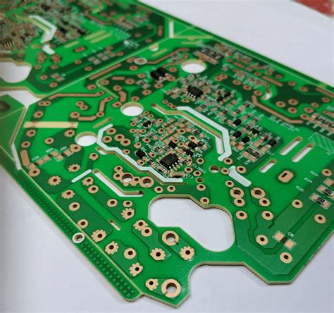
2. PCB Stackup Design for Power Integrity
A well-designed PCB stackup is fundamental for power integrity. Considerations include:
A. Power and Ground Planes
- Use dedicated power and ground planes to minimize impedance and provide low-inductance return paths.
- Avoid splitting planes unnecessarily, as this increases loop inductance.
- Ensure sufficient copper thickness to handle current demands.
B. Layer Arrangement
- Place power and ground planes adjacent to each other to enhance capacitance and reduce loop inductance.
- High-speed signal layers should be sandwiched between ground planes to minimize EMI.
C. Dielectric Material Selection
- Choose materials with low dielectric loss (Df) and stable dielectric constant (Dk) to minimize signal degradation.
- FR-4 is common, but high-speed designs may require specialized laminates like Rogers or Isola.
3. Power Distribution Network (PDN) Optimization
The PDN must deliver clean power with minimal impedance. Key techniques include:
A. Low-Impedance Power Delivery
- Use wide power traces to reduce resistance (IR drop).
- Implement multiple vias for power connections to lower inductance.
- Employ power islands for high-current components.
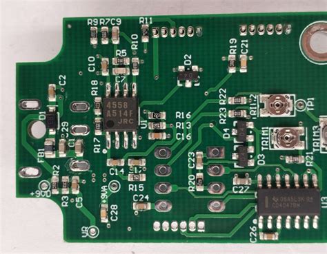
B. Decoupling Capacitors
- Place bulk capacitors (10-100µF) near voltage regulators to handle low-frequency noise.
- Use ceramic capacitors (0.1µF, 0.01µF) near ICs to suppress high-frequency noise.
- Follow the “rule of thumb” for decoupling: one capacitor per power pin.
C. Power Plane Segmentation
- Separate analog and digital power domains to prevent noise coupling.
- Use ferrite beads or inductors for isolation between power sections.
4. Minimizing Ground Noise and Return Paths
Ground integrity is as crucial as power integrity. Poor grounding leads to noise and EMI.
A. Solid Ground Planes
- Use uninterrupted ground planes to provide low-impedance return paths.
- Avoid split grounds unless necessary (e.g., analog/digital separation).
B. Proper Return Path Design
- Ensure high-speed signals have a continuous return path beneath them.
- Avoid slotting ground planes, which increases inductance.
C. Grounding Techniques
- Star Grounding: Connect all ground returns to a single point to avoid ground loops.
- Multi-point Grounding: Used in high-frequency designs to reduce impedance.
5. Managing High-Speed Signals and Power Integrity
High-speed signals can introduce noise into the PDN. Mitigation strategies include:
A. Controlled Impedance Routing
- Match trace impedance to prevent reflections (e.g., 50Ω for single-ended, 100Ω for differential).
- Use microstrip or stripline configurations for consistent impedance.
B. Crosstalk Reduction
- Increase spacing between high-speed traces.
- Use guard traces or ground shielding to isolate sensitive signals.
C. Via Optimization
- Minimize via stubs to reduce signal reflections.
- Use back-drilling for high-speed signals in multilayer PCBs.
6. Simulation and Analysis for Power Integrity
Simulation tools help predict and mitigate power integrity issues before fabrication.
A. DC Analysis (IR Drop)
- Tools like Cadence Allegro, ANSYS SIwave, and Altium Designer can simulate voltage drops.
- Identify high-resistance areas and optimize trace widths.
B. AC Analysis (Impedance & Resonance)
- Perform frequency-domain simulations to analyze PDN impedance.
- Identify anti-resonances and adjust decoupling strategies.
C. Transient Analysis (SSN & Ground Bounce)
- Simulate switching noise to evaluate decoupling effectiveness.
- Use time-domain reflectometry (TDR) for signal integrity checks.
7. Best Practices for Maintaining Power Integrity
A. Proper Component Placement
- Place voltage regulators close to power-hungry components.
- Group related components to minimize loop area.
B. Minimizing Loop Inductance
- Keep power and ground paths short and wide.
- Use multiple vias for parallel current paths.
C. Thermal Management
- Ensure adequate copper pour for heat dissipation.
- Use thermal vias to transfer heat to inner layers.
D. Testing & Validation
- Measure power ripple with an oscilloscope.
- Perform PDN impedance measurements using a vector network analyzer (VNA).
Conclusion
Maintaining power integrity in PCB design requires a holistic approach, from stackup planning to simulation and testing. By optimizing the power distribution network, minimizing ground noise, and employing effective decoupling strategies, engineers can ensure stable power delivery and reliable system performance. As electronic devices continue to evolve, adhering to these best practices will be crucial for successful PCB designs.
By implementing these techniques, designers can mitigate power-related issues, reduce EMI, and enhance the overall functionality of their circuits. Whether working on high-speed digital systems or sensitive analog designs, maintaining power integrity remains a cornerstone of robust PCB engineering.