How to Remove Header Pins from a PCB: A Comprehensive Guide
Introduction
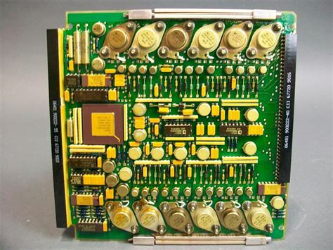
Printed Circuit Boards (PCBs) form the backbone of modern electronics, and header pins are among the most common components used to create connections between different boards or external devices. Whether you’re reworking a prototype, salvaging components, or repairing existing equipment, knowing how to properly remove header pins from a PCB is an essential skill for any electronics enthusiast or professional. This 2000-word guide will walk you through all aspects of the header pin removal process, covering tools, techniques, safety considerations, and troubleshooting tips.
Understanding Header Pins and Their Connections
Before attempting to remove header pins, it’s important to understand how they’re attached to the PCB:
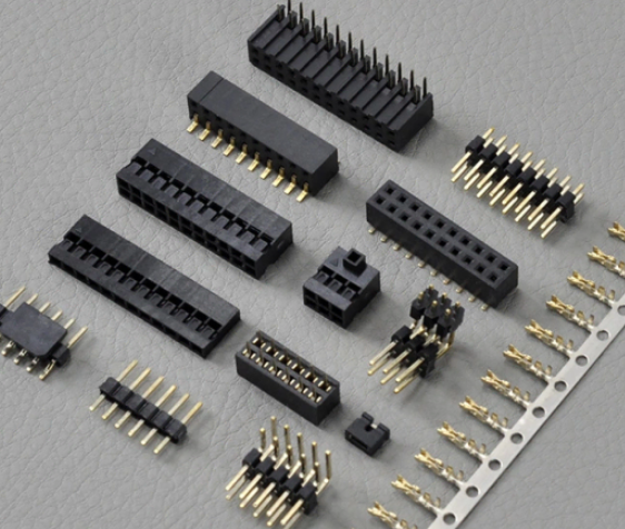
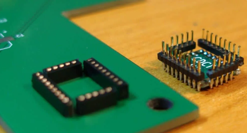
Through-hole headers are the most common type, with pins that pass through drilled holes in the PCB and are soldered on the opposite side. These typically require desoldering for removal.
Surface-mount headers are soldered directly to pads on one side of the PCB. These can be more challenging to remove without proper tools.
Press-fit headers use mechanical tension rather than solder for connection, though these are less common in hobbyist projects.
The removal method you choose will depend on the header type, the PCB’s construction, and the tools available to you.
Essential Tools for Header Pin Removal
Having the right tools makes the removal process significantly easier and reduces the risk of damaging your PCB:
- Soldering Iron: A temperature-controlled iron with appropriate tips (chisel or conical) is fundamental. For most header pins, a 30-60W iron works well.
- Desoldering Tools:
- Solder sucker (manual plunger type)
- Desoldering braid (copper wick)
- Desoldering pump (electric)
- Hot air rework station (for surface-mount headers)
- Support Tools:
- Tweezers or small pliers
- Flush cutters
- PCB holder or vise
- Magnifying glass or microscope
- Heat-resistant mat
- Safety Equipment:
- Safety glasses
- Heat-resistant gloves
- Fume extractor or well-ventilated area
Step-by-Step Guide to Removing Through-Hole Header Pins
Method 1: Using a Solder Sucker
- Secure the PCB: Place the board on a stable, heat-resistant surface. A PCB holder or vise helps prevent movement.
- Heat the Solder Joint: Apply your soldering iron (set to about 300-350°C) to the solder joint where the pin meets the PCB. Allow the solder to fully melt (2-4 seconds typically).
- Remove the Molten Solder:
- For a solder sucker: Quickly place the tip near (but not touching) the joint and press the release button to suck up the molten solder.
- For desoldering braid: Place the braid over the joint and apply the iron on top. The braid will wick away the solder through capillary action.
- Repeat as Needed: Most joints will require multiple passes to remove enough solder for pin extraction.
- Free the Pin: Once most solder is removed, gently wiggle the pin while heating any remaining solder. The pin should become loose enough to pull out with tweezers.
Method 2: Using a Hot Air Rework Station
- Protect Surrounding Components: Use kapton tape or aluminum foil to shield nearby components from heat.
- Apply Heat: Set your hot air gun to about 300-350°C with medium airflow. Apply heat evenly across all pins of the header.
- Remove the Header: Once the solder melts (after 20-40 seconds typically), use tweezers to gently lift the header straight up from the board.
Removing Surface-Mount Headers
Surface-mount headers require more finesse to remove without damaging PCB pads:
- Apply Flux: Adding flux helps heat transfer and solder flow.
- Simultaneous Heating:
- Using two soldering irons: Heat both ends of the header simultaneously while lifting.
- Using hot air: Heat the entire header evenly until solder melts, then lift gently with tweezers.
- Clean Up: Remove any remaining solder from pads using desoldering braid.
Advanced Techniques
For stubborn headers or high-density boards, consider these methods:
Solder Pot Method: For multi-pin headers, briefly dipping the solder side into a solder pot (at about 300°C) can melt all joints simultaneously, allowing quick removal. This requires proper equipment and safety precautions.
Low-Temperature Alloy: Adding a low-melting-point alloy to the existing solder can lower the overall melting temperature, making removal easier.
Pin-by-Pin Removal: For large headers where entire removal is difficult, you can sometimes cut the plastic header body and remove pins individually.

Common Challenges and Solutions
- Broken Pins in Holes:
- Apply heat and use a dental pick or small drill bit to extract the remnant.
- As a last resort, carefully drill out the pin with a bit slightly smaller than the hole.
- Lifted Pads:
- If a pad lifts during removal, clean the area and consider using a jumper wire to recreate the connection.
- Plastic Header Melting:
- Work quickly to minimize heat exposure to the plastic.
- Consider cutting the plastic away first if the header is being discarded.
- Multi-row Headers:
- Remove one row at a time to maintain alignment.
- Consider using a removal tool that fits over the entire header.
Post-Removal PCB Care
After removing headers:
- Clean the Area: Use isopropyl alcohol and a brush to remove flux residues.
- Inspect Holes: Ensure all holes are clear of solder or debris. Use a toothpick or small drill bit if needed.
- Check for Damage: Look for lifted traces or damaged pads that may need repair.
- Prepare for Reuse: If installing a new header, ensure holes are properly tinned or cleaned.
Safety Considerations
- Ventilation: Work in a well-ventilated area to avoid inhaling solder fumes.
- Eye Protection: Wear safety glasses to protect against flying solder or debris.
- Heat Management: Be aware of hot components and tools to prevent burns.
- ESD Protection: Use an antistatic mat and wrist strap when working with sensitive components.
Tips for Easier Header Removal
- Add Fresh Solder: Sometimes adding a small amount of fresh solder to old joints can improve heat transfer.
- Use the Right Tip: A chisel tip often works better than a conical tip for desoldering.
- Pre-heat the Board: For multilayer boards, slight pre-heating (100-150°C) can prevent heat sinking issues.
- Work Methodically: Tackle one pin at a time, ensuring each is fully free before moving to the next.
When to Seek Professional Help
Consider professional PCB rework services if:
- You’re working with expensive or irreplaceable boards
- The PCB has more than 2 layers
- You lack the proper tools
- There’s significant damage during removal attempts
Conclusion
Removing header pins from a PCB requires patience, the right tools, and proper technique. Whether you’re using basic hand tools or advanced rework stations, the key principles remain the same: adequate heat control, thorough solder removal, and gentle handling of the PCB. With practice and attention to detail, you can master this essential electronics rework skill. Always prioritize safety and don’t hesitate to practice on scrap boards before working on valuable projects. As you gain experience, you’ll develop your own techniques and preferences for different header removal scenarios.