How to Solder Double-Sided PCB: A Comprehensive Guide
Soldering a double-sided printed circuit board (PCB) can be a challenging task, especially for beginners. However, with the right tools, techniques, and a bit of practice, you can master the art of soldering double-sided PCBs. This guide will walk you through the entire process, from preparation to finishing touches, ensuring that you achieve a reliable and professional result.
Table of Contents
- Introduction to Double-Sided PCBs
- Tools and Materials Required
- Preparation Before Soldering
- Soldering Techniques for Double-Sided PCBs
- 4.1. Soldering Through-Hole Components
- 4.2. Soldering Surface-Mount Components
- Common Challenges and How to Overcome Them
- Post-Soldering Inspection and Testing
- Conclusion
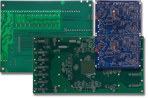
1. Introduction to Double-Sided PCBs
Double-sided PCBs are circuit boards that have conductive copper layers on both the top and bottom sides. These layers are connected by vias, which are small holes drilled through the board and plated with conductive material. Double-sided PCBs are widely used in electronics because they allow for more complex circuits and higher component density compared to single-sided PCBs.
Soldering double-sided PCBs requires careful attention to detail, as you need to ensure that both sides of the board are properly connected and that there are no solder bridges or cold joints. This guide will help you navigate the process step by step.
2. Tools and Materials Required
Before you start soldering, it’s essential to gather all the necessary tools and materials. Here’s a list of what you’ll need:
- Soldering Iron: A temperature-controlled soldering iron with a fine tip is ideal for precision work.
- Solder: Use high-quality rosin-core solder with a diameter appropriate for your components (typically 0.5mm to 1mm).
- Flux: Flux helps the solder flow and adhere to the components and PCB pads. Liquid or paste flux is commonly used.
- Desoldering Tools: Desoldering braid or a solder sucker can be useful for correcting mistakes.
- Tweezers: Fine-tipped tweezers are essential for handling small components, especially surface-mount devices (SMDs).
- Magnifying Glass or Microscope: A magnifying tool can help you inspect small solder joints and components.
- PCB Holder: A PCB holder or vise will keep the board steady while you work.
- Cleaning Supplies: Isopropyl alcohol and a brush or sponge for cleaning the PCB after soldering.
- Safety Gear: Safety glasses and a well-ventilated workspace are important to protect your eyes and lungs from solder fumes.
3. Preparation Before Soldering
Proper preparation is key to successful soldering. Follow these steps before you start:
3.1. Clean the PCB
Ensure that the PCB is clean and free of dust, grease, or oxidation. Use isopropyl alcohol and a soft brush or cloth to clean the board. Any contamination can lead to poor solder joints.
3.2. Inspect the Components
Check all components for damage or defects. Ensure that the leads are straight and that there are no bent pins on through-hole components. For SMDs, verify that the pads on the PCB match the component’s footprint.
3.3. Organize Your Workspace
Set up your workspace with all the tools and materials within easy reach. Ensure that your soldering iron is heated to the appropriate temperature (typically between 300°C and 350°C for lead-based solder, or slightly higher for lead-free solder).
3.4. Apply Flux (Optional)
Applying a small amount of flux to the pads can improve solder flow and adhesion. This is especially useful for surface-mount components.
4. Soldering Techniques for Double-Sided PCBs
Soldering double-sided PCBs involves working on both the top and bottom sides of the board. The techniques differ slightly depending on whether you’re soldering through-hole or surface-mount components.
4.1. Soldering Through-Hole Components
Through-hole components have leads that pass through holes in the PCB and are soldered on the opposite side. Here’s how to solder them:
Step 1: Insert the Component
Insert the component leads through the appropriate holes on the PCB. Ensure that the component is seated correctly and that the leads are protruding through the other side.
Step 2: Bend the Leads (Optional)
To hold the component in place, you can gently bend the leads outward on the opposite side of the board. This prevents the component from falling out when you flip the board.
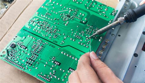
Step 3: Apply Solder
Heat the soldering iron and touch it to the pad and the component lead simultaneously. After a second or two, apply solder to the joint. The solder should flow smoothly and form a concave fillet around the lead. Avoid using too much solder, as this can create bridges between adjacent pads.
Step 4: Trim the Leads
Once the solder joint has cooled, use a pair of wire cutters to trim the excess lead length. Be careful not to damage the solder joint.
Step 5: Repeat for the Other Side
Flip the board and repeat the process for the other side. Ensure that the solder joints on both sides are clean and well-formed.
4.2. Soldering Surface-Mount Components
Surface-mount components (SMDs) are soldered directly onto the surface of the PCB. Soldering SMDs requires more precision, but with practice, it becomes manageable.
Step 1: Apply Solder Paste (Optional)
For small SMDs, you can apply a small amount of solder paste to the pads using a syringe or stencil. This helps hold the component in place and ensures good solder flow.
Step 2: Place the Component
Using tweezers, carefully place the SMD onto the pads. Ensure that the component is aligned correctly. For larger SMDs, you may need to hold the component in place while soldering.
Step 3: Solder One Pad
Heat the soldering iron and touch it to one of the pads. Apply a small amount of solder to create a temporary joint. This will hold the component in place while you solder the other pads.
Step 4: Solder the Remaining Pads
Once the component is held in place, solder the remaining pads. Use the soldering iron to heat the pad and the component lead simultaneously, then apply solder. Ensure that the solder flows smoothly and forms a good joint.
Step 5: Inspect and Reflow (if necessary)
Inspect the solder joints under a magnifying glass or microscope. If any joints look incomplete or have solder bridges, use the soldering iron to reflow the solder and correct the issue.
5. Common Challenges and How to Overcome Them
Soldering double-sided PCBs can present several challenges. Here are some common issues and how to address them:
5.1. Solder Bridges
Solder bridges occur when solder accidentally connects two adjacent pads or leads. To fix this, use desoldering braid or a solder sucker to remove the excess solder. You can also use flux to help the solder flow away from the bridge.
5.2. Cold Joints
Cold joints happen when the solder doesn’t melt completely, resulting in a weak or unreliable connection. To fix a cold joint, reheat the joint with the soldering iron and apply a small amount of fresh solder.
5.3. Tombstoning
Tombstoning is a common issue with SMDs, where one end of the component lifts off the pad during soldering. This is often caused by uneven heating or incorrect solder paste application. To prevent tombstoning, ensure that both pads are heated evenly and that the component is placed correctly.
5.4. Overheating
Overheating can damage components or the PCB itself. To avoid this, use a temperature-controlled soldering iron and limit the amount of time the iron is in contact with the PCB.
6. Post-Soldering Inspection and Testing
After soldering, it’s crucial to inspect and test your work to ensure that everything is functioning correctly.
6.1. Visual Inspection
Use a magnifying glass or microscope to inspect all solder joints. Look for any signs of solder bridges, cold joints, or incomplete connections. Ensure that all components are properly seated and aligned.
6.2. Electrical Testing
Use a multimeter to test for continuity between connected pads and components. Check for any short circuits or open connections. If you find any issues, reflow the solder joints or use desoldering tools to correct the problem.
6.3. Functional Testing
If possible, power up the PCB and test its functionality. Verify that all components are working as expected and that the circuit performs its intended function.
6.4. Cleaning
Finally, clean the PCB with isopropyl alcohol to remove any flux residue. This will help prevent corrosion and ensure the long-term reliability of the board.
7. Conclusion
Soldering double-sided PCBs requires patience, precision, and practice. By following the steps outlined in this guide, you can achieve professional-quality solder joints and reliable connections on both sides of the board. Remember to take your time, use the right tools, and inspect your work carefully. With experience, you’ll become more confident and efficient in soldering double-sided PCBs, opening up new possibilities for your electronic projects.


