How to Test for Short Circuits on a PCB: A Comprehensive Guide
Introduction
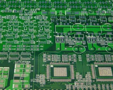
Printed Circuit Boards (PCBs) are the backbone of modern electronics, found in everything from smartphones to industrial machinery. One of the most common and potentially damaging issues in PCB manufacturing and repair is the presence of short circuits. These unintended connections between different conductive paths can cause equipment malfunctions, component damage, or even safety hazards. This 2000-word guide will explore various methods for testing and identifying short circuits on PCBs, ranging from basic visual inspections to advanced diagnostic techniques.
Understanding PCB Short Circuits
Before diving into testing methods, it’s essential to understand what constitutes a short circuit on a PCB:
Definition: A short circuit (or “short”) occurs when two or more points in an electrical circuit that should not be connected come into direct contact, creating a low-resistance path for current to flow. This bypasses the intended circuit path and can lead to excessive current flow.
Common Causes:
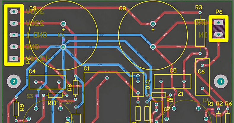
- Solder bridges between adjacent pads or traces
- Damaged insulation or conductive debris on the board
- Incorrect component placement
- Manufacturing defects in the PCB itself (like copper cladding issues)
- Component failure creating internal shorts
- Mechanical damage to the board (cracks, flexing)
Effects of Short Circuits:
- Excessive current draw leading to overheating
- Component malfunction or failure
- Voltage drops in other parts of the circuit
- Complete system failure
- Potential fire hazards in extreme cases
Visual Inspection: The First Line of Defense
1. Basic Visual Examination
Always begin with a thorough visual inspection under good lighting:
- Examine both sides of the PCB carefully
- Use magnification (3x to 10x) for small components
- Look for obvious solder bridges between pins or pads
- Check for damaged or burnt components
- Inspect for stray wires or conductive debris
- Look for damaged or lifted traces
- Verify all polarized components are correctly oriented
2. Special Lighting Techniques:
- Use angled lighting to spot solder bridges (shadows help reveal connections)
- Try darkfield illumination to highlight surface imperfections
- Consider UV light to detect certain types of contamination
3. Common Visual Short Circuit Indicators:
- Discolored or charred areas on the PCB
- Bulging or leaking components
- Melted solder mask
- Visible metal whiskers between conductors
- Physical damage to the board or components
Continuity Testing with a Multimeter
When visual inspection doesn’t reveal the short, a digital multimeter (DMM) is the next tool to employ.
1. Setting Up Your Multimeter:
- Select the continuity or resistance (Ω) mode
- For continuity: the meter will beep when resistance is below a threshold (typically 10-50Ω)
- For resistance: look for very low readings between points that should not be connected
2. Testing Methodology:
- Power off the PCB completely and discharge capacitors
- Identify all power and ground planes/connections
- Start by checking between power and ground (should show high resistance)
- If power-ground shows short, begin systematic isolation:
- Remove power connections and test again
- Remove suspicious components one by one
- Divide the board into sections (split-half method)
3. Advanced Continuity Testing Techniques:
- Use needle probes for precise point-to-point testing
- Create a “map” of expected connections for complex boards
- Test adjacent traces and pins on connectors
- Check between different voltage rails if applicable
Using a Milliohmmeter for Precision Measurement
When dealing with very low resistance shorts that a standard multimeter can’t reliably detect, a milliohmmeter provides better resolution.
How It Works:
- Applies a known current and measures voltage drop
- Can detect resistances in the milliohm range
- Helps identify “partial shorts” that might not trigger continuity beep
Application:
- Useful for detecting hairline solder bridges
- Can identify shorted windings in transformers/inductors
- Helps locate shorts in power planes or thick traces
Thermal Imaging and Hotspot Detection
Short circuits often generate heat, making thermal imaging a valuable diagnostic tool.
Methods:
- Passive Thermal Imaging:
- Power the board normally
- Use an IR camera to identify unexpected hot spots
- Compare with known-good board if available
- Active Thermal Imaging with Current Injection:
- Inject limited current (100mA-1A) through the short
- Monitor temperature rise with thermal camera
- The short location will typically heat up fastest
Advantages:
- Non-contact method
- Can scan entire boards quickly
- Works for intermittent shorts that occur under power
Limitations:
- Requires some current flow to generate heat
- May miss very low-power shorts
- Thermal cameras can be expensive
Using a Short Circuit Finder or Tracer
Dedicated short circuit locator tools offer specialized functionality:
1. Tone Generator Method:
- Injects an AC signal at the short point
- Use a sensitive probe to “sniff” the signal
- Signal strength indicates proximity to short
2. Pulse Response Method:
- Sends fast pulses and analyzes reflections
- Works similarly to time-domain reflectometry (TDR)
- Can estimate distance to short location
3. Magnetic Field Detection:
- Detects current-induced magnetic fields
- Particularly useful for power plane shorts
- Can trace current paths through the board
The Alcohol Evaporation Technique
For stubborn shorts that are difficult to locate, this low-tech method can be surprisingly effective:
Procedure:
- Apply isopropyl alcohol to the powered PCB
- The short circuit will generate heat
- Alcohol evaporates fastest at the hottest point
- Watch for the area where alcohol dries first
Tips:
- Use high-concentration (90%+) alcohol
- Apply with a brush or spray bottle
- Works best on unpopulated areas of the board
- Can be combined with thermal imaging
Advanced Techniques for Complex PCBs
For multilayer boards or complex systems, more sophisticated approaches may be necessary:
1. X-ray Inspection:
- Reveals internal layer shorts
- Shows solder defects under BGA packages
- Requires specialized (and expensive) equipment
2. Time-Domain Reflectometry (TDR):
- Sends high-frequency pulses and measures reflections
- Can pinpoint short location within millimeters
- Requires expensive equipment and expertise
3. Flying Probe Testing:
- Automated system tests thousands of points
- Creates a complete connectivity map
- Compares against known-good profile
4. Current Imaging:
- Uses sensitive magnetic field sensors
- Creates a map of current flow through the board
- Can identify unexpected current paths
Repairing Identified Short Circuits
Once located, shorts can typically be repaired:
Common Repair Methods:
- Solder bridges: Remove excess solder with wick or vacuum tool
- Conductive debris: Clean with isopropyl alcohol and brush
- Damaged traces: Repair with jumper wires or conductive ink
- Internal layer shorts: May require board replacement or careful drilling
- Component shorts: Replace the faulty component
Prevention Tips:
- Always follow proper soldering techniques
- Maintain a clean work environment
- Use adequate spacing in PCB design
- Implement proper design rules (DRC) checks
- Consider protective coatings for harsh environments
Conclusion
Testing for and identifying short circuits on PCBs requires a systematic approach combining multiple techniques. Start with simple visual inspection and basic continuity tests, then progress to more advanced methods as needed. The complexity of modern electronics often demands creative problem-solving and sometimes specialized equipment. By understanding and applying these various testing methodologies, technicians and engineers can efficiently locate and repair short circuits, reducing downtime and improving product reliability.
Remember that prevention is always better than cure—proper design practices, careful manufacturing, and thorough quality control can minimize short circuit issues before they occur. However, when shorts do appear, this comprehensive set of testing approaches will help you track them down and restore your PCB to proper functionality.