Introduction to PCB Inspection Methods
This article explains how process monitoring can prevent PCB defects and improve overall quality.
Inspection can often remind you that your PCB assembly process has too many variables. Even after your manufacturing process can achieve consistent zero-defect production, some form of inspection or monitoring is necessary to ensure the desired quality level. Surface mount assembly is a very complex series of events and a large number of individual actions. The trick is to establish a balanced inspection and monitoring strategy without 100% inspection. This article discusses inspection methods, techniques and manual inspection tools, as well as reviews automated inspection tools and using inspection results (number and type of defects) to improve process and product quality.
Inspection is a product-centric activity, while monitoring is a process-centric activity.
Both are needed for a quality program, but the long-term goal should be less product inspection and more process monitoring. Product inspection is reactive (defects have already occurred), while process monitoring is proactive (defects can be prevented) – obviously, prevention is much more valuable than reactive response to existing defects.
Inspection is really a screening process because it attempts to identify unacceptable products to repair.
It is clear that mass inspection does not necessarily improve or ensure product quality. The third of Deming’s fourteen points says, “Don’t count on mass inspection.” Deming emphasized that a strong process should focus on establishing stable, repeatable, statistically monitored process goals rather than mass inspection. Inspection is a subjective activity and a difficult task even with a considerable degree of training. In many cases, you can call a group of inspectors to evaluate a weld and get several different opinions.
Operator fatigue is why 100% inspection usually does not find every manufacturing defect, and it is a costly, non-value-added operation. It rarely achieves the desired goals of higher product quality and customer satisfaction.
Several years ago, we began using the term “process monitoring” instead of inspectors because we wanted to change the mindset of the production floor from reactive to proactive. An inspector typically sits at the end of the assembly line and inspects the product. In an ideal situation, process monitoring activities are a balance between product inspection and process monitoring – for example, confirming that the correct process parameters are being used, measuring machine performance, and creating and analyzing control charts. Process monitors take a leadership role in these activities; they help machine operators accomplish these tasks. Training is a key factor. Process monitors and machine operators must understand process standards (e.g., IPC-A-610), the concepts of process monitoring, and related tools (e.g., control charts, Pareto charts, etc.). Process monitors also promote product quality and process monitoring. As a key member of the manufacturing team, monitors encourage a defect prevention approach rather than a find-and-fix approach.
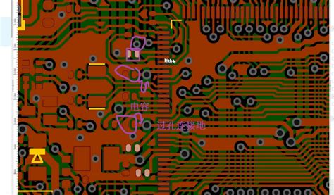
Over-inspection is also a common problem.
In many cases, over-inspection is simply the result of a misplaced understanding of IPC-A-610 process standards. For example, for insert mounted components, many inspectors also want perfect solder fillets on both sides of the board and completely filled through holes. However, this is not required by IPC-A-610. Inspection quality fluctuates with the inspector’s level of attention and concentration. For example, fear (management pressure) may increase the level of attention on the production floor, and quality may improve for a period of time. However, if mass inspection is the primary inspection method, defective products may still be produced and may leave the factory.
Another term we should avoid is touch-up.
Many employees throughout the industry believe that touch-up is a normal and acceptable part of the assembly process. This is very unfortunate because any form of rework and repair should be viewed as undesirable. Rework is often viewed as undesirable, but it is a necessary message to instill throughout the manufacturing organization. It is important to establish a manufacturing environment where defects and rework are viewed as avoidable and least desired.
For most companies, manual inspection is the first line of defense.
Inspectors use a variety of magnification tools to get a closer look at components and solder joints. IPC-A-610 establishes some basic magnification guidelines based on the width of the pads of the components being inspected. The main reason for these guidelines is to avoid over-inspection due to excessive magnification. For example, if the pad width is 0.25~0.50 mm, then the desired magnification is 10X, and 20X can be used as a reference if necessary.
Every inspector has a favorite inspection tool; a good one is a three-lens folding pocket magnifier used by machinists. It can be carried with you and has a maximum magnification of 12X, which is just right for fine-pitch solder joints. Perhaps the most common inspection tool is a microscope, which has a magnification range of 10-40X. However, microscopes cause fatigue when used continuously, which often leads to over-inspection because the magnification usually exceeds the guidelines of IPC-A-610. Of course, they are still useful when a close inspection of possible defects is needed.
For general inspection, a video system with a variable zoom lens (4-30X) and a high-definition color monitor is preferred.
These systems are easy to use and, more importantly, less fatigue-prone than a microscope. High-quality video systems cost less than $2,000, and good microscopes are also in this price range. The added benefit of a video system is that more than one person can see the object, which is helpful during training or when the inspector needs a second opinion. Edmund Scientific (edmundscientific.com) has a large number of magnification tools, from handheld magnifiers to microscopes to video systems.
In summary, establishing a balanced monitoring strategy between 0-100% inspection is a challenge. From this point, the key inspection points, we will discuss the inspection equipment.
Automation is fantastic; in many cases, more accurate, faster and more efficient than an inspector. But it can be quite expensive, depending on its sophistication. Automated inspection equipment may dilute human awareness and give a false sense of security.
Solder Paste Inspection. Solder paste printing is a complex process that can easily deviate from the desired results.
A clearly defined and properly executed process monitoring strategy is required to keep the process under control. At a minimum, manual inspection of coverage and thickness measurements are required, but automated coverage, thickness and volume measurements are preferably used. Use range control charts (X-bar R charts) to record the results.
Solder Paste Inspection Equipment ranges from simple 3X magnifiers to expensive automatic in-line machines. Level 1 tools use optical or lasers to measure thickness, while Level 2 tools use lasers to measure coverage, thickness and volume. Both tools are used offline. Level 3 tools also measure coverage, thickness and volume, but are installed in-line. The speed, accuracy, and repeatability of these systems vary, depending on price. More expensive tools offer better performance.
For most assembly lines, especially high-mix production, the preferred mid-level performance is an off-line, bench-mounted tool that measures coverage, thickness, and volume. These tools offer flexibility, cost less than $50,000, and generally provide the desired amount of feedback. Obviously, automated tools are much more expensive ($75,000 – $200,000). However, they are faster and more convenient to inspect boards because they are installed in-line. They are best suited for high-volume, low-mix assembly lines.
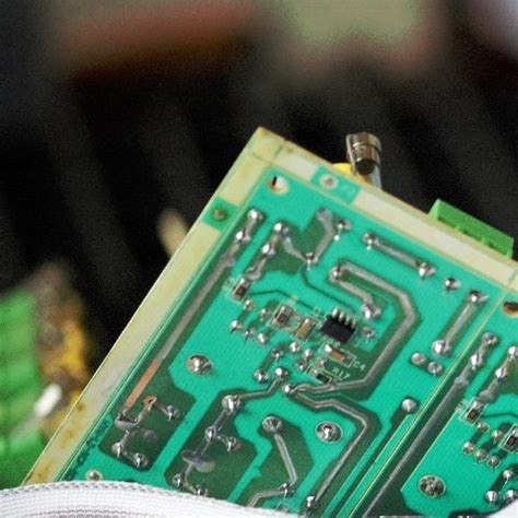
Glue Inspection.
Glue dispensing is another complex process that is prone to deviations from the desired results. As with solder paste printing, a clearly defined and properly executed process monitoring strategy is required to keep the process under control. Manual inspection of glue dot diameter is recommended. Use an X-bar R chart to record the results.
It is a good idea to place at least two isolated glue dots on the board before and after a glue dispensing cycle to represent each dot diameter. This allows the operator to compare the quality of the glue dots during the glue cycle. The dots can also be used to measure the diameter of the glue dots. Glue dot inspection tools are relatively inexpensive and are basically portable or desktop measuring microscopes. It is not known that there are any automatic equipment designed specifically for glue dot inspection. Some automated optical inspection (AOI) machines can be adapted to perform this task, but it may be overkill.
First-article validation.
Companies usually perform a detailed inspection of the first board off the assembly line to verify the machine settings. This method is slow, passive and inaccurate. It is common to see a complex board with at least 1,000 components, many of which are not marked (value, part number, etc.). This makes inspection difficult. Verifying the machine settings (components, machine parameters, etc.) is a proactive approach. AOI can be effectively used for first-article inspection. Some hardware and software suppliers also provide feeder setting validation software.
Coordinating the verification of machine settings is an ideal role for a process monitor who walks the machine operators through the line validation process with the help of a checklist. In addition to verifying the feeder settings, the process monitor should carefully check the first two boards using the tools available. After reflow, the process monitor should perform a quick but detailed check of critical components (fine pitch components, BGAs, polarized capacitors, etc.). Meanwhile, the line continues to assemble boards. To reduce downtime, the line should be fully loaded with boards before reflow while the process monitor checks the first two boards after reflow. This can be a bit dangerous, but the confidence to do so can be gained by verifying the machine settings.
X-ray Inspection.
Based on experience, X-ray is not necessarily mandatory for BGA assembly. However, it is certainly a good tool to have on hand if you can afford it. It should be recommended for CSP assembly. X-ray is very good for checking for solder shorts, but not so good for finding solder opens. Low-cost X-ray machines can only look down and are adequate for checking for solder shorts. X-ray machines that can tilt the object under inspection are better for checking for opens.
Automated Optical Inspection (AOI).
Ten years ago, optical inspection was used as a tool that could solve everyone’s quality problems. The technology was later discontinued because it could not keep pace with assembly technology. In the past five years, it has re-emerged as a desirable technology. A good process monitoring strategy should include overlapping tools such as in-circuit testing (ICT), optical inspection, functional testing, and visual inspection. These processes overlap and complement each other, and none of them can provide adequate coverage alone.
Two-dimensional (2-D) AOI machines can check for missing components, misalignment, incorrect part numbers, and reversed polarity. In addition, three-dimensional (3-D) machines can evaluate the quality of solder joints. Several suppliers offer desktop, 2-D AOI machines for less than $50,000. These machines are ideal for initial product inspection and small-volume sample programs. In the higher-performance category, 2-D stand-alone or in-line machines cost $75,000-$125,000, while 3-D machines cost $150,000-$250,000. AOI technology has considerable promise, but processing speed and programming time are still a limiting factor.
Data collection is one thing, but using that data to improve performance and reduce defects is the ultimate goal.
Unfortunately, many companies collect a lot of data without using it effectively. Reviewing and analyzing data can be laborious, and it is common to see this task performed only by engineering and design personnel, excluding production activities. Without accurate feedback, production proceeds blindly. Weekly quality meetings can be an effective way for engineering and production departments to communicate key information and drive necessary improvements. These meetings require a leader, must be well organized, and are especially short (30 minutes or less). The data presented in these meetings must be user-friendly and meaningful (for example, Pareto charts). When a problem is identified, an investigator must be assigned immediately. Meeting leaders must take accurate notes to ensure a successful conclusion. Closure means root causes and corrective actions.


