Introduction to rigid flex pcb material
Flex PCB materials need to support multiple design and operational goals: static or dynamic flexing, ability to pass through standard
assembly processes, and support for simple fabrication procedures with high yield.
Flex PCB materials may seem exotic at first, but a relatively small material set is used to produce flex and rigid-flex PCBs at high volume. In this guide, we’ll examine some of the basic properties of flex PCB materials and how they are used to build flex/rigid-flex PCBs.

Adhesives
Traditionally, adhesives are required for bonding the copper foil to PI (or other) films, because unlike a typical FR-4 rigid board, there’s less “
tooth” in the annealed copper, and heat & pressure alone are not enough to form a reliable bond.
Manufacturers such offer pre-laminated single- and double-sided copper clad films for flexible circuit etching, using acrylic or epoxy based adhesives with typical thicknesses of ½ and 1 mil. The adhesives are specially developed for flexibility.
“Adhesiveless” laminates are becoming more prevalent due to newer processes that involve copper plating or deposition directly onto the PI
film. These films are chosen when finer pitches and smaller vias are needed as in HDI circuits.
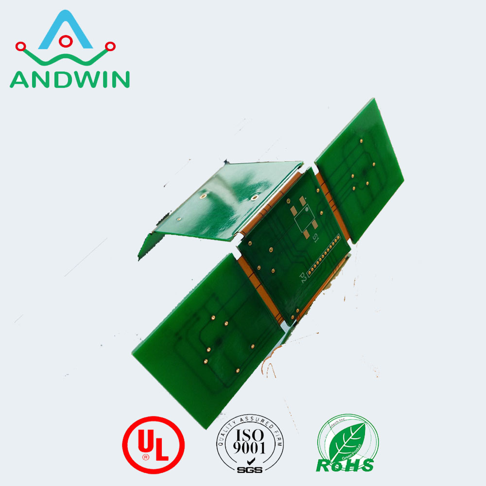
Silicones, hot-melt glues, and epoxy resins are also used when protective beads are added to the flex-to-rigid joins or interfaces (i.e. where
the flexible part of the layer stack leaves the rigid part).
These offer mechanical reinforcement to the fulcrum of the flex-to-rigid join which otherwise would rapidly fatigue and crack or tear in repeated use.

Conductors
While the above-mentioned cheap electronics may use printed conductors – usually some kind of carbon film or silver based ink – copper is the most typical conductor of choice. Depending upon the application different forms of copper need to be considered.
If you are simply using the flexible part of the circuit to reduce manufacturing time and costs by removing cabling and connectors, then the usual laminated
copper foil (Electro-Deposited, or ED) for rigid board use is fine.
This may also be used where heavier copper weights are desired to keep high-current carrying conductors to the minimum viable width, as in planar inductors.
But copper is also infamous for work-hardening and fatigue. If your final application involves repeated creasing or movement of the flex circuit you need to consider higher-grade Rolled Annealed (RA) foils. Obviously the added step of annealing the foil adds to the cost considerably.
But the annealed copper is able to stretch more before fatigue cracking occurs, and is springier in the Z deflection direction – exactly what you want for a flex circuit that will be bending or rolling all the time. This is because the rolling annealing process elongates the grain structure in the planar direction.
If you are simply using the flexible part of the circuit to reduce manufacturing time and costs by removing cabling and connectors, then the usual laminated copper foil for rigid board use is fine.

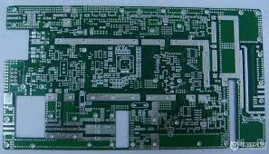
Substrate and Coverlay Films
The base material used in most common rigid printed circuit boards is woven fibreglass impregnated in epoxy resin. It’s actually a fabric, and although we term these “rigid” if you take a single laminate layer they have a reasonable amount of elasticity.
It’s the cured epoxy which makes the board more rigid. Because of the use of epoxy resins, they are often referred to as organic rigid printed circuit boards.
This is not flexible enough for many applications though for simple assemblies where there’s not going to be constant movement it can be suitable.