Ipc standard for pcb assembly
Understanding IPC-A-610: The Essential Standard for PCB Assembly Quality
In the realm of electronics manufacturing, ensuring the quality and reliability of printed circuit board (PCB) assemblies is paramount. The IPC-A-610 standard, developed by the Association Connecting Electronics Industries, serves as a critical benchmark for assessing the acceptability of electronic assemblies.
This standard is widely recognized and adopted across the industry, providing a comprehensive set of criteria that manufacturers and inspectors use to evaluate the quality of PCB assemblies.
Understanding the nuances of IPC-A-610 is essential for anyone involved in the production or inspection of electronic assemblies, as it directly impacts the performance and longevity of electronic devices.
IPC-A-610 is often referred to as the “Acceptability of Electronic Assemblies” standard.
It provides detailed visual and descriptive criteria for a wide range of assembly attributes, including soldering, component placement, and mechanical assembly. The standard categorizes defects and conditions into three classes, each representing different levels of quality and reliability requirements. Class 1 is the least stringent, suitable for general electronic products where function is the primary concern. Class 2 is more rigorous, intended for products where continued performance and extended life are required, but uninterrupted service is not critical. Class 3 is the most stringent, reserved for high-performance electronic products where continued performance or performance-on-demand is critical, such as in aerospace or medical applications.
Transitioning to the specifics, IPC-A-610 covers a broad spectrum of assembly processes and materials.
It addresses soldering criteria for through-hole and surface mount technologies, providing detailed guidelines on acceptable and non-acceptable conditions. For instance, it specifies the acceptable range for solder fillet height and width, ensuring that solder joints are robust and reliable. Additionally, the standard outlines criteria for component placement, emphasizing the importance of proper alignment and orientation to prevent functional failures. It also includes guidelines for mechanical assembly, such as the acceptability of fasteners and connectors, which are crucial for maintaining the structural integrity of the assembly.
Moreover, IPC-A-610 is not static; it evolves to keep pace with technological advancements and industry needs.
Regular updates ensure that the standard remains relevant, incorporating new materials, processes, and technologies. This adaptability is crucial in an industry characterized by rapid innovation and change. For instance, recent revisions have addressed the challenges posed by lead-free soldering and the miniaturization of components, reflecting the industry’s shift towards more environmentally friendly and compact designs.
In addition to providing a framework for quality assessment, IPC-A-610 serves as a valuable training tool.
It is widely used in certification programs to educate and certify assembly operators, inspectors, and engineers. By familiarizing themselves with the standard, professionals can enhance their understanding of quality requirements and improve their ability to identify and rectify defects. This, in turn, contributes to higher quality products and greater customer satisfaction.
In conclusion, IPC-A-610 is an indispensable standard in the electronics manufacturing industry, offering a comprehensive set of criteria for evaluating the quality of PCB assemblies. Its detailed guidelines and classification system enable manufacturers to produce reliable and high-quality electronic products. As technology continues to evolve, IPC-A-610 remains a vital resource, adapting to new challenges and ensuring that quality standards keep pace with industry advancements. Understanding and adhering to this standard is essential for anyone involved in the production or inspection of electronic assemblies, as it directly influences the performance and reliability of the final product.
IPC J-STD-001: Best Practices for Soldering in PCB Assembly
IPC J-STD-001 is a critical standard in the realm of printed circuit board (PCB) assembly, providing comprehensive guidelines for soldering processes. This standard is widely recognized and adopted across the electronics manufacturing industry, serving as a benchmark for quality and reliability in soldered electrical and electronic assemblies. As technology continues to evolve, the importance of adhering to such standards cannot be overstated, as they ensure the functionality and longevity of electronic devices.
To begin with, IPC J-STD-001 outlines the materials, methods, and verification criteria necessary for producing high-quality soldered connections.
It emphasizes the importance of selecting appropriate soldering materials, such as solder alloys and fluxes, which are crucial for achieving optimal results. The standard specifies the characteristics of these materials, ensuring they meet the necessary requirements for various applications. By adhering to these guidelines, manufacturers can prevent common issues such as poor wetting, insufficient solder joints, and corrosion, which can compromise the performance of the final product.
Moreover, the standard provides detailed instructions on soldering techniques, which are essential for achieving consistent and reliable connections.
It covers various soldering methods, including hand soldering, wave soldering, and reflow soldering, each with its own set of best practices. For instance, in hand soldering, the standard emphasizes the importance of maintaining the correct temperature and using the appropriate tip size to ensure proper heat transfer. Similarly, in wave and reflow soldering, it highlights the significance of controlling the process parameters, such as conveyor speed and temperature profiles, to achieve uniform soldering across all components.
In addition to materials and techniques, IPC J-STD-001 also addresses the importance of cleanliness in the soldering process.
Contaminants such as dust, oils, and residues can adversely affect solderability and lead to defects. Therefore, the standard recommends thorough cleaning of both the components and the PCB before soldering. It also suggests post-soldering cleaning to remove any flux residues that might remain, which could potentially cause corrosion or electrical leakage over time. By maintaining a clean environment, manufacturers can significantly reduce the risk of defects and enhance the reliability of the assembly.
Furthermore, inspection and testing are integral components of the IPC J-STD-001 standard.
It provides criteria for evaluating the quality of soldered connections, including visual inspection guidelines and acceptance criteria for various types of joints. The standard also encourages the use of advanced inspection techniques, such as X-ray and automated optical inspection (AOI), to detect hidden defects that might not be visible to the naked eye. By implementing rigorous inspection and testing procedures, manufacturers can ensure that their products meet the highest quality standards and function as intended in their respective applications.
In conclusion, IPC J-STD-001 serves as an essential guide for best practices in soldering within PCB assembly. By adhering to its guidelines on materials, techniques, cleanliness, and inspection, manufacturers can produce reliable and high-quality electronic assemblies. As the electronics industry continues to advance, the role of such standards becomes increasingly vital in ensuring that products meet the ever-growing demands for performance and reliability. Consequently, IPC J-STD-001 remains a cornerstone in the pursuit of excellence in PCB assembly, fostering innovation while maintaining the highest standards of quality.
The Role of IPC-7711/7721 in PCB Assembly Rework and Repair
In the realm of printed circuit board (PCB) assembly, maintaining the integrity and functionality of electronic components is paramount. As technology advances, the complexity of PCBs increases, necessitating stringent standards to ensure quality and reliability. One such critical standard is the IPC-7711/7721, which plays a pivotal role in the rework and repair of PCBs. This standard, developed by the Institute for Printed Circuits (IPC), provides comprehensive guidelines that are essential for technicians and engineers involved in the rework and repair processes.
IPC-7711/7721 is a dual standard, with IPC-7711 focusing on rework, which involves the removal and replacement of components, and IPC-7721 addressing repair, which pertains to the restoration of a PCB to its original functionality.
These standards are indispensable in the electronics industry, where the demand for high-quality and reliable products is ever-increasing. By adhering to these guidelines, manufacturers can ensure that their products meet the necessary quality benchmarks, thereby enhancing customer satisfaction and reducing the likelihood of product failures.
One of the primary benefits of IPC-7711/7721 is its detailed procedural instructions, which cover a wide range of rework and repair scenarios.
These procedures are meticulously designed to minimize damage to the PCB and its components, thereby preserving the board’s integrity. For instance, the standard provides specific techniques for desoldering and soldering components, which are crucial in preventing thermal damage and ensuring proper electrical connections. Moreover, it includes guidelines for handling and replacing surface mount devices (SMDs) and through-hole components, which are common in modern PCBs.
In addition to procedural instructions, IPC-7711/7721 emphasizes the importance of using appropriate tools and materials.
The standard outlines the necessary equipment for various rework and repair tasks, such as soldering irons, hot air rework stations, and microscopes. It also specifies the types of solder and flux that should be used to achieve optimal results. By following these recommendations, technicians can perform rework and repair tasks more efficiently and effectively, reducing the risk of further damage to the PCB.
Furthermore, IPC-7711/7721 highlights the significance of operator training and certification.
Given the intricate nature of PCB rework and repair, it is crucial that technicians possess the requisite skills and knowledge to execute these tasks proficiently. The standard advocates for comprehensive training programs that cover both theoretical and practical aspects of rework and repair. By ensuring that operators are well-trained and certified, manufacturers can maintain high standards of quality and reliability in their products.
Another critical aspect of IPC-7711/7721 is its focus on documentation and traceability.
The standard mandates thorough documentation of all rework and repair activities, including the identification of defects, the methods used for correction, and the final inspection results. This documentation is vital for maintaining traceability and accountability, allowing manufacturers to track the history of each PCB and identify any recurring issues. Consequently, this facilitates continuous improvement in the rework and repair processes, ultimately leading to enhanced product quality.
In conclusion, IPC-7711/7721 serves as an indispensable guide for PCB assembly rework and repair, providing detailed procedures, emphasizing the use of appropriate tools and materials, advocating for operator training, and underscoring the importance of documentation. By adhering to this standard, manufacturers can ensure the quality and reliability of their products, thereby meeting the ever-evolving demands of the electronics industry. As technology continues to advance, the role of IPC-7711/7721 in maintaining PCB integrity will remain crucial, safeguarding the performance and longevity of electronic devices.
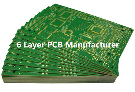
How IPC-6012 Ensures Reliability in Rigid PCB Fabrication and Assembly
The IPC-6012 standard plays a pivotal role in ensuring the reliability and quality of rigid printed circuit boards (PCBs), which are integral components in a wide array of electronic devices. As technology continues to advance, the demand for high-performance and dependable PCBs has become increasingly critical. The IPC-6012 standard, developed by the Institute for Printed Circuits (IPC), provides comprehensive guidelines and requirements for the fabrication and assembly of rigid PCBs, thereby ensuring that these components meet the necessary quality and performance benchmarks.
To begin with, the IPC-6012 standard outlines specific criteria for the materials and processes used in the fabrication of rigid PCBs.
This includes detailed specifications for the base materials, such as copper-clad laminates, which are essential for the electrical performance and mechanical stability of the boards. By adhering to these material specifications, manufacturers can ensure that the PCBs possess the necessary thermal, electrical, and mechanical properties to function reliably in various applications. Furthermore, the standard addresses the importance of maintaining stringent process controls during fabrication, which helps in minimizing defects and ensuring consistency across production batches.
In addition to material and process specifications, IPC-6012 emphasizes the importance of thorough testing and inspection procedures.
These procedures are crucial for identifying potential defects and ensuring that the PCBs meet the required performance standards. The standard specifies various testing methods, such as electrical continuity tests, insulation resistance tests, and thermal stress tests, which are designed to evaluate the integrity and reliability of the PCBs under different conditions. By implementing these testing protocols, manufacturers can detect and rectify issues early in the production process, thereby reducing the risk of failures in the final product.
Moreover, IPC-6012 provides guidelines for the classification of PCBs based on their intended application and performance requirements.
This classification system helps manufacturers and end-users to select the appropriate PCB type for their specific needs, ensuring that the boards are capable of withstanding the environmental and operational stresses they will encounter. For instance, PCBs used in aerospace or medical applications may require higher reliability and performance standards compared to those used in consumer electronics. By categorizing PCBs according to their application, the standard facilitates better decision-making and enhances the overall reliability of electronic systems.
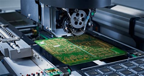
Transitioning to the assembly phase, IPC-6012 also addresses the critical aspects of PCB assembly, including soldering processes and component placement.
The standard provides guidelines for ensuring proper solder joint quality, which is essential for the electrical connectivity and mechanical stability of the assembled PCBs. By adhering to these guidelines, manufacturers can minimize the risk of solder joint failures, which are a common cause of PCB malfunctions. Additionally, the standard emphasizes the importance of proper component placement and alignment, which are crucial for the functionality and reliability of the final product.
In conclusion, the IPC-6012 standard serves as a comprehensive framework for ensuring the reliability and quality of rigid PCBs throughout their fabrication and assembly processes. By providing detailed guidelines for materials, processes, testing, and assembly, the standard helps manufacturers produce PCBs that meet the stringent demands of modern electronic applications. As technology continues to evolve, adherence to IPC-6012 will remain essential for ensuring the performance and dependability of electronic devices across various industries.

