Mastering Thermal Management in Multilayer Metal Core PCB Design
Key Takeaways
When designing multilayer metal core PCBs, understanding thermal management principles is critical to balancing performance and reliability. Here’s what you need to prioritize:
- Thermal conductivity directly impacts heat dissipation efficiency. Materials like aluminum or copper cores are preferred, but your choice must align with cost constraints and application requirements.
- Structural stability relies on layer stacking precision. Poor alignment can create thermal stress points, leading to delamination or warping during operation.
- EMI shielding benefits from strategic metal core placement. Integrating ground planes adjacent to signal layers minimizes interference while aiding heat transfer.
"A well-designed metal core PCB acts as both a circuit carrier and a heat sink, but only if material properties and layout synergize."
For pcb manufacturing companies, balancing pcb manufacturing cost with performance involves:
| Factor | High-Cost Impact | Cost-Saving Strategy |
|---|---|---|
| Core Material | Copper (>8W/mK) | Aluminum (2-3W/mK) |
| Layer Count | Complex thermal vias | Optimized via density |
| Surface Finish | ENIG (enhanced durability) | HASL (budget-friendly) |
If you’re managing a pcb manufacturing business, consider these tips:
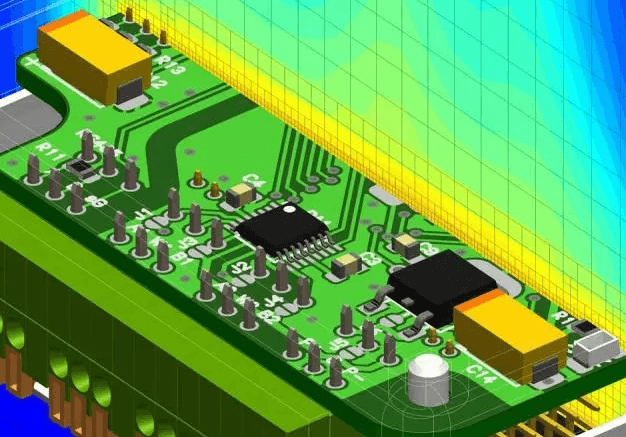
- Use simulation tools like ANSYS or COMSOL to model heat distribution before prototyping.
- Collaborate with suppliers early to negotiate pcb manufacturing bulk pricing for metal substrates.
- Prioritize designs that minimize thermal cycling—a major cause of solder joint failure.
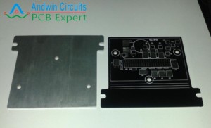
For advanced thermal strategies, explore hybrid designs combining metal cores with ceramic-filled dielectrics. Companies like Andwin PCB specialize in high-temperature solutions, offering tailored advice for optimizing pcb manufacturing cost without compromising reliability. Always validate thermal performance through infrared imaging or CFD analysis post-production.

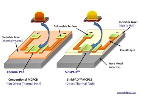
Thermal Management Fundamentals for MCPCBs
Effective thermal management starts with understanding how heat propagates through a multilayer metal core PCB (MCPCB). Unlike traditional FR4 boards, PCB manufacturing for MCPCBs relies on thermally conductive dielectric layers and metal substrates—typically aluminum or copper—to dissipate heat from high-power components. Critical design decisions, such as substrate thickness and dielectric material selection, directly impact thermal conductivity and structural integrity. For instance, opting for a thicker aluminum core improves heat spreading but may increase PCB manufacturing cost due to material expenses and machining complexity.
When designing for heat dissipation, consider how component placement interacts with the metal core’s thermal pathways. Power devices like LEDs or MOSFETs should be positioned directly over the metal substrate to minimize thermal resistance. Advanced PCB manufacturing companies often use simulation tools to model heat distribution, ensuring hotspots are mitigated before prototyping. This proactive approach reduces iterative design cycles, balancing PCB manufacturing business efficiency with performance requirements.
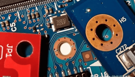
Another key factor is the integration of thermal vias—plated holes that transfer heat between layers. While these enhance cooling, overusing them can compromise mechanical stability. Striking this balance requires aligning your layout strategy with the metal core’s properties. For example, copper’s higher thermal conductivity (385 W/mK vs. aluminum’s 205 W/mK) allows fewer vias but raises material costs. Here, collaborating with experienced PCB manufacturing partners becomes vital to optimize designs without exceeding budget constraints.
Finally, don’t overlook the role of surface finishes and solder mask materials in thermal management. Ceramic-filled coatings or high-temperature solder masks can improve heat resistance, protecting sensitive components in high-density layouts. By addressing these fundamentals early, you ensure your MCPCB design achieves both thermal efficiency and long-term reliability.
Structural Stability in Multilayer PCB Design
When designing multilayer metal core PCBs, ensuring structural stability isn’t just about mechanical integrity—it directly impacts thermal performance and long-term reliability. Thermal expansion mismatches between materials like aluminum cores, copper layers, and dielectric substrates can warp boards or delaminate traces under repeated heating cycles. To mitigate this, pcb manufacturing companies prioritize material compatibility analysis, often opting for alloys with similar coefficients of thermal expansion (CTE) to minimize stress buildup.
Balancing pcb manufacturing cost with performance requires strategic layer stacking. For instance, placing high-power components closer to the metal core improves heat dissipation but demands precise alignment to avoid uneven pressure distribution. Advanced pcb manufacturing techniques, such as laser-drilled microvias and symmetric layer arrangements, enhance rigidity while maintaining optimal signal integrity. You’ll also need to account for mechanical fastening points—improper placement can concentrate stress, leading to cracks in solder joints or substrate layers.
In high-temperature environments, structural flaws amplify pcb manufacturing business risks like premature device failure. Using finite element analysis (FEA) simulations during prototyping helps identify weak points in the design phase. Reinforcing edges with thicker copper pours or adding stiffener bars around heat-generating components are common solutions. However, over-engineering increases material costs, so collaborating with experienced pcb manufacturing partners ensures a balance between durability and budget constraints.
Finally, don’t overlook the role of surface finishes. Electroless nickel immersion gold (ENIG) or hard gold plating not only improves solderability but also adds a protective layer against thermal cycling fatigue. These choices, while marginally raising pcb manufacturing cost, pay dividends in applications where vibration resistance and thermal endurance are non-negotiable. By integrating structural considerations early in the design workflow, you create boards that withstand both thermal and mechanical challenges without compromising performance.
EMI Shielding Techniques Using Metal Cores
When designing multilayer metal core PCBs, managing electromagnetic interference (EMI) becomes critical for maintaining signal integrity and device reliability. The metal core itself acts as a natural shield, but optimizing its effectiveness requires strategic design choices. By leveraging the conductive properties of materials like aluminum or copper, you create a Faraday cage effect that redirects EMI away from sensitive components. This approach is particularly valuable in high-frequency applications where PCB manufacturing processes must balance cost and performance.
One effective method involves integrating ground planes directly into the metal core layers. These planes absorb and dissipate electromagnetic noise, reducing crosstalk between adjacent circuits. For cost-sensitive projects, collaborating with experienced PCB manufacturing companies helps identify the optimal balance between shielding effectiveness and PCB manufacturing cost. Advanced techniques like split-core designs or segmented shielding zones allow targeted EMI suppression without over-engineering the entire board.
Thermal vias play a dual role here: they enhance heat dissipation while creating electrical connections that improve shielding continuity. When working with PCB manufacturing business partners, specify via fill materials with high thermal conductivity, such as silver epoxy, to maximize both thermal and EMI performance. Remember that uneven metal core thickness can create impedance mismatches, so rigorous simulation tools are essential during prototyping.
For applications requiring extreme shielding, consider hybrid stacks combining traditional FR-4 layers with metal cores. This configuration isolates noise-prone sections while maintaining flexibility in PCB manufacturing. Always validate designs through real-world EMI testing—what works in simulation might need adjustments when exposed to actual operating conditions. By prioritizing shielding early in the design phase, you avoid costly revisions and ensure compliance with industry standards for electromagnetic compatibility.
Advanced Heat Dissipation Strategies Explored
When implementing thermal management in multilayer metal core PCB designs, you’ll need to move beyond basic heat-spreading techniques. Modern high-power applications demand a combination of passive and active cooling methods tailored to your board’s unique thermal profile. Start by optimizing thermal via arrays—strategically placing them under high-heat components like power converters or LEDs creates low-resistance paths for heat transfer to the metal core. For designs requiring localized cooling, consider embedding microchannel heat sinks directly into the metal substrate, which can reduce hotspot temperatures by up to 30% compared to traditional layouts.
Another approach involves leveraging hybrid material stacks—pairing aluminum or copper cores with thermally conductive dielectric layers—to balance electrical insulation and heat dissipation. Top-tier PCB manufacturing companies often use laser-drilled cavities filled with thermally conductive epoxy to bridge heat-generating components to the metal base. This method minimizes thermal expansion mismatches while maintaining structural integrity, a critical factor when managing PCB manufacturing costs in complex multilayer builds.
Active cooling solutions, such as integrating piezoelectric fans or thermoelectric coolers (TECs), become essential for applications like automotive electronics or industrial controllers. These components work synergistically with the metal core to redirect heat away from sensitive areas, but they require precise placement to avoid interfering with EMI shielding layers. Simulation tools like finite element analysis (FEA) help validate thermal gradients before prototyping, ensuring your design aligns with both performance goals and PCB manufacturing business constraints.
Don’t overlook the role of surface finishes in heat dissipation. Electroless nickel immersion gold (ENIG) or hard anodized coatings can enhance thermal radiation efficiency without compromising solderability. For high-frequency designs, combine these finishes with embedded thermal pads to create localized cooling zones. Balancing these strategies requires collaboration with your PCB manufacturing partner early in the design phase, as material choices directly impact thermal resistance and production scalability.
Finally, iterative testing under real-world conditions remains irreplaceable. Use infrared thermography to identify residual heat buildup and refine your layout iteratively. By integrating these advanced techniques, you’ll achieve a thermally robust design that meets stringent reliability standards without inflating PCB manufacturing cost or complexity.
High-Temperature Electronics Cooling Solutions
When designing multilayer metal core PCBs for high-temperature environments, managing heat dissipation becomes a critical balancing act. You need solutions that not only prevent thermal runaway but also maintain electrical integrity and mechanical durability. Start by evaluating active versus passive cooling methods. Active systems like microfluidic cooling channels or integrated heat pipes excel in applications requiring precise temperature control, but they often increase pcb manufacturing cost due to added complexity. Passive approaches—such as strategic placement of thermal vias or copper-filled trenches—offer a cost-effective alternative while preserving structural stability.
Collaboration with experienced pcb manufacturing companies is essential here. Their expertise in material compatibility ensures that thermal interface materials (TIMs) like ceramic-filled adhesives or graphene-enhanced pads align with your design’s thermal expansion coefficients. For instance, embedding aluminum nitride (AlN) substrates in the metal core can enhance heat spreading without compromising EMI shielding performance—a common pain point in high-density layouts.
Don’t overlook the role of pcb manufacturing business logistics in thermal strategy. Bulk procurement of high-conductivity dielectric layers or pre-bonded copper clads can reduce unit costs, especially for prototypes. Advanced simulation tools like finite element analysis (FEA) allow you to model heat distribution patterns early, avoiding costly redesigns post-production.
Finally, consider hybrid approaches. Pairing passive heatsinks with localized active cooling zones lets you target hotspots efficiently. This is particularly valuable in power electronics or LED systems, where uneven thermal loads threaten solder joint reliability. By integrating these strategies during the pcb manufacturing phase, you ensure scalability and compliance with industry-specific thermal derating standards.
Material Selection for Optimal Thermal Performance
Choosing the right materials is critical for balancing thermal efficiency and structural integrity in multilayer metal core PCBs. When working with high-temperature electronics, the base metal layer’s thermal conductivity directly impacts heat dissipation. Aluminum (130-170 W/mK) and copper (385 W/mK) are common choices, but their selection depends on thermal budget constraints and pcb manufacturing cost considerations. For instance, aluminum cores offer a cost-effective solution for moderate heat loads, while copper excels in applications demanding rapid heat transfer—though it raises material expenses.
The dielectric layer’s properties are equally vital. Opt for ceramic-filled polymers or advanced epoxy resins with thermal conductivities above 2.5 W/mK to minimize thermal resistance between layers. Leading pcb manufacturing companies often recommend materials like polyimide or FR-4 hybrids for their balanced dielectric strength and heat dissipation capabilities. However, thicker dielectric layers may reduce thermal vias efficiency, requiring careful simulation during design.
When sourcing materials, prioritize suppliers specializing in pcb manufacturing business workflows, as they can provide tailored solutions for multilayer stacking. For example, anodized aluminum substrates improve corrosion resistance in humid environments, while copper-invar-copper (CIC) laminates mitigate thermal expansion mismatches. These choices influence not just performance but also long-term reliability—a key factor in pcb manufacturing quality audits.
Cost optimization requires strategic trade-offs. High-performance ceramics or specialty alloys might elevate pcb manufacturing cost by 15-30%, but they prevent failures in high-power LED or automotive systems. Collaborate with fabricators early to align material specs with production feasibility, ensuring your design meets both thermal and budgetary targets without compromising EMI shielding or layer adhesion.
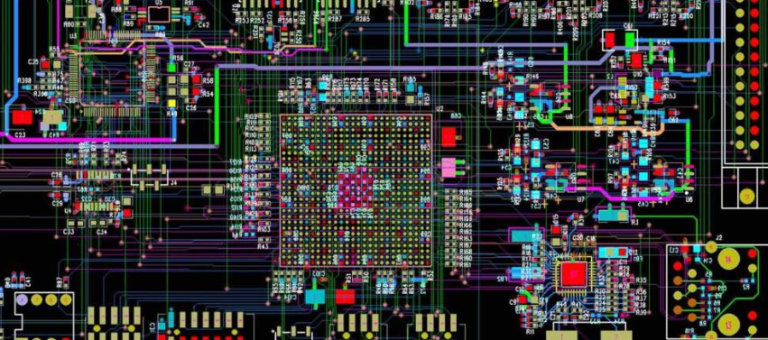
Metal Core PCB Layout Best Practices
When designing multilayer metal core PCBs, your layout decisions directly influence thermal performance, manufacturing feasibility, and long-term reliability. Start by optimizing PCB manufacturing compatibility—collaborate with PCB manufacturing companies early to align your design with their process capabilities. For instance, balancing copper distribution across layers ensures even heat dissipation while minimizing warpage risks during assembly.
Prioritize thermal vias and thermal relief patterns near high-power components to channel heat toward the metal core. However, avoid overcrowding these features, as excessive via drilling can compromise the core’s structural integrity. Instead, use simulation tools to model heat flow and validate placement before finalizing the design. This proactive approach reduces PCB manufacturing cost by minimizing trial-and-error iterations.
Layer stacking plays a critical role in managing electromagnetic interference (EMI). Position the metal core as an inner layer to act as a shield, but ensure adjacent dielectric materials have sufficient thermal conductivity. For example, pairing aluminum cores with ceramic-filled prepregs enhances heat transfer without sacrificing signal integrity. When selecting materials, consider how their coefficients of thermal expansion (CTE) align—mismatched CTEs between layers can lead to delamination under thermal stress, a common pitfall in high-temperature applications.
Trace routing demands equal attention. Keep high-current paths short and wide to reduce resistive heating, and isolate sensitive analog circuits from noisy digital sections using the metal core as a ground plane. This technique not only improves EMI performance but also simplifies thermal management by creating predictable heat dissipation pathways.
Finally, engage with your PCB manufacturing business partner to review design-for-manufacturability (DFM) guidelines. Subtle adjustments—like adjusting solder mask openings or optimizing component spacing—can enhance yield rates without compromising functionality. Remember, a well-executed layout balances thermal efficiency, manufacturability, and cost-effectiveness, ensuring your multilayer metal core PCB performs reliably in even the most demanding environments.
Ensuring Reliability Through Thermal Analysis
Effective thermal analysis begins with understanding how heat propagates through multilayer metal core PCBs during operation. When designing high-power circuits, you’ll need to map thermal gradients across layers using simulation tools to identify hotspots that could compromise performance. PCB manufacturing companies often employ finite element analysis (FEA) to predict heat distribution, ensuring your design aligns with material limits and operational requirements. By integrating these insights early, you reduce the risk of delamination or warping—critical for maintaining structural stability in high-temperature environments.
Balancing PCB manufacturing cost with thermal efficiency requires strategic material choices. For instance, selecting aluminum cores over copper might lower expenses but demands careful evaluation of their thermal conductivity trade-offs. Advanced PCB manufacturing business models leverage hybrid stacks—combining insulated metal substrates with traditional FR-4—to optimize heat dissipation without inflating budgets. During prototyping, validate your thermal vias’ placement and density, as uneven heat paths can create mechanical stress points, accelerating failure in mission-critical applications.
Collaboration with PCB manufacturing partners becomes pivotal here. Share your thermal simulation data to refine layer stackups or adjust copper weights, ensuring the final design meets both thermal and EMI shielding benchmarks. Post-production, employ infrared thermography to verify real-world performance, comparing results against initial models. This iterative process not only enhances reliability but also streamlines compliance with industry standards for high-temperature electronics.
Finally, consider how thermal analysis intersects with long-term durability. Components like power transistors or LEDs generate sustained heat, which, if unmanaged, degrades solder joints and dielectric layers over time. By embedding thermal relief patterns and optimizing component spacing, you mitigate these risks while maintaining PCB manufacturing cost efficiency. Remember, a robust thermal strategy isn’t just about cooling—it’s about creating a system where heat flows predictably, preserving both functionality and lifespan.
Conclusion
Effective thermal management in multilayer metal core PCB design hinges on balancing technical precision with strategic collaboration. When partnering with PCB manufacturing companies, it’s critical to communicate your thermal requirements early to align material choices, layer configurations, and fabrication techniques with performance goals. Structural stability and EMI shielding aren’t just design features—they’re outcomes of meticulous planning, from selecting thermally conductive substrates to optimizing trace layouts for heat dissipation.
While PCB manufacturing cost often drives decision-making, prioritizing quality in materials like aluminum or copper cores pays dividends in high-temperature reliability and long-term durability. Advanced strategies, such as integrating thermal vias or embedding heat sinks, require close coordination with your manufacturer to avoid compromising PCB manufacturing business timelines or budgets. Remember, simulations and thermal analysis tools are indispensable for predicting hotspots and validating designs before production.
Ultimately, the success of your multilayer metal core PCB hinges on harmonizing thermal management with electrical performance. By integrating EMI mitigation techniques like grounded metal cores and shielding layers, you create boards that withstand both thermal stress and electromagnetic interference. As you refine your approach, leverage the expertise of PCB manufacturing partners to navigate trade-offs between cost, complexity, and performance—ensuring your designs meet the rigorous demands of modern high-power applications.
FAQs
How does thermal management differ in multilayer metal core PCBs compared to standard designs?
In multilayer metal core PCBs, heat dissipation occurs through conductive layers (typically aluminum or copper) that transfer heat away from critical components. Unlike standard FR4 boards, these designs prioritize thermal conductivity by embedding metal cores, reducing reliance on external cooling systems. This approach directly impacts pcb manufacturing cost due to specialized materials and layered structuring.
What structural challenges arise when integrating EMI shielding in metal core PCBs?
Balancing EMI shielding effectiveness with structural integrity requires precise layer stacking. While metal cores inherently block electromagnetic interference, improper alignment during pcb manufacturing can create thermal stress points. Partnering with experienced pcb manufacturing companies ensures optimal layer bonding and shielding performance without compromising heat dissipation.
How do material choices affect thermal performance in high-temperature applications?
Selecting metals with high thermal conductivity (e.g., copper) improves heat transfer but increases pcb manufacturing cost. For cost-sensitive projects, aluminum cores offer a balance between performance and affordability. Advanced pcb manufacturing business solutions now combine ceramic-filled dielectrics with metal substrates to enhance thermal stability in extreme environments.
Can multilayer metal core PCBs reduce reliance on external cooling systems?
Yes. By embedding thermally conductive layers, these PCBs distribute heat more efficiently, minimizing hotspots. However, thermal analysis simulations during the pcb manufacturing phase are critical to validate design choices. This reduces long-term costs by avoiding post-production modifications.
What design practices optimize thermal reliability in multilayer metal core layouts?
- Isolate high-power components near metal cores for direct heat transfer
- Use thermal vias to connect heat-generating areas to the core layer
- Prioritize symmetrical layer stacking to prevent warping during pcb manufacturing
Ready to Optimize Your Multilayer Metal Core PCB Design?
Explore tailored solutions for high-temperature applications and cost-efficient thermal management. For expert guidance on balancing pcb manufacturing cost with performance, please click here to consult our engineering team.