Metal Core PCB Prototype Structural Design Essentials
Key Takeaways
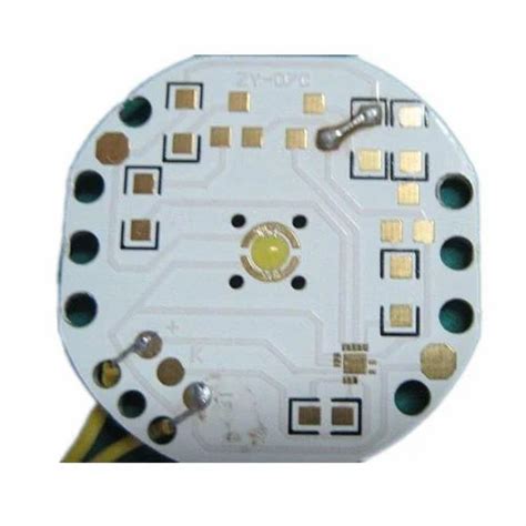
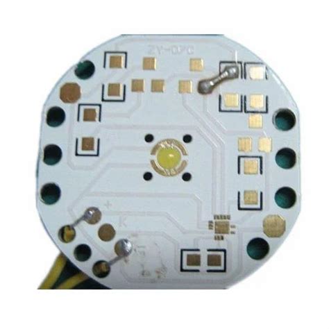
When designing metal core PCB prototypes, focus on three pillars: thermal efficiency, structural durability, and EMI mitigation. Start by evaluating heat dissipation pathways—thicker copper layers or aluminum substrates often outperform standard FR-4 materials in high-power scenarios. Partnering with experienced PCB manufacturing companies ensures access to advanced materials like ceramic-filled dielectrics, which reduce PCB manufacturing cost while boosting thermal conductivity.
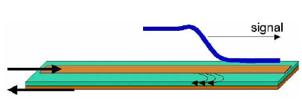
For EMI shielding, integrate ground planes or ferrite-based coatings early in your layout. This minimizes redesign cycles and aligns with lean PCB manufacturing business practices. Prioritize symmetrical layer stackups to prevent warping, especially in designs exposed to thermal cycling. Remember: a well-configured heat spreader can lower operating temperatures by up to 30%, directly extending component lifespan.
Balancing performance and budget requires iterative prototyping. Test different metal core thicknesses and dielectric constants to find the sweet spot between thermal management and PCB manufacturing feasibility. Always validate designs under simulated high-load conditions—this reveals weaknesses in solder joints or via placements before full-scale production.
Thermal Management in Metal Core PCBs
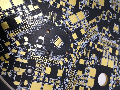
Effective thermal management begins with understanding how heat flows through your metal core PCB prototype. Unlike traditional FR4 boards, metal-clad designs channel heat away from critical components via a conductive base layer—typically aluminum or copper. To optimize this process, you must balance PCB manufacturing cost with performance by selecting materials that match your application’s thermal demands. For example, aluminum offers a cost-effective solution for moderate heat loads, while copper excels in high-power scenarios despite its higher material expense.
Tip: Always collaborate with PCB manufacturing companies early in the design phase to validate thermal simulations. This avoids costly revisions during production.
| Design Factor | Aluminum Core | Copper Core |
|---|---|---|
| Thermal Conductivity (W/mK) | 2–4 | 380–400 |
| Cost per Square Inch | $0.8–$1.2 | $2.5–$3.5 |
| Ideal Application | LED Lighting | Power Converters |
When planning layer stackups, position high-heat components directly above the metal core to minimize thermal resistance. Use thermal vias to enhance heat dissipation to outer layers or heatsinks, but avoid overcrowding them, as this can weaken structural integrity. For PCB manufacturing business stakeholders, reducing PCB manufacturing defects requires strict adherence to dielectric layer thickness tolerances—even minor variations can disrupt heat transfer paths.
Integrating advanced thermal interface materials between the PCB and external cooling systems further improves efficiency. However, ensure your design accounts for coefficient of thermal expansion (CTE) mismatches to prevent delamination during temperature cycling. By prioritizing these factors, you create prototypes that withstand rigorous operational conditions while maintaining scalability for mass production.
Material Selection for Optimal Heat Dissipation
Choosing the right materials forms the foundation of effective thermal management in metal core PCB prototypes. While aluminum remains the most common base material due to its balanced thermal conductivity and lightweight properties, copper-clad alternatives offer superior heat dissipation for high-power-density applications. When evaluating PCB manufacturing options, prioritize substrates with dielectric layers that combine electrical insulation with minimal thermal resistance—ceramic-filled or epoxy-based materials often strike this balance.
Work closely with PCB manufacturing companies to validate material compatibility with your operating environment. For instance, polyimide-based dielectrics excel in high-temperature scenarios, whereas aluminum nitride substrates provide exceptional thermal transfer in compact designs. Keep PCB manufacturing cost in check by avoiding over-specification: thicker metal cores or premium alloys may not always justify their price if your application doesn’t require extreme thermal thresholds.
Remember, material choices directly influence PCB manufacturing business logistics. Opting for standardized metal cores simplifies sourcing and reduces lead times, while specialty materials might demand custom tooling. Always cross-reference thermal simulation data with real-world testing to ensure your selections align with both performance goals and production feasibility.
EMI Shielding Strategies for High-Power Designs
When designing metal core PCB prototypes for high-power applications, addressing electromagnetic interference (EMI) is critical to ensure signal integrity and compliance with regulatory standards. Grounding techniques play a pivotal role here—integrating a low-impedance ground plane into the metal core structure helps dissipate unwanted noise. You can enhance shielding effectiveness by using conductive coatings or embedding Faraday cages around sensitive components. For PCB manufacturing companies, balancing PCB manufacturing cost with performance often involves selecting materials like aluminum or copper alloys, which offer inherent EMI suppression while maintaining thermal conductivity.
Another key strategy is optimizing trace routing to minimize loop areas and coupling paths. Pairing this with shielded vias or edge plating reduces radiation leakage at board edges. When collaborating with PCB manufacturing partners, clarify their capabilities in applying selective solder masks or EMI-absorbing laminates to avoid unexpected PCB manufacturing business delays. Remember, inadequate shielding not only risks electromagnetic compatibility (EMC) failures but also escalates long-term PCB manufacturing cost due to redesigns. By prioritizing these strategies early, you ensure robustness in high-density, high-power environments while aligning with industry benchmarks.
Structural Integrity in High-Temperature Environments
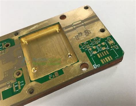
When designing metal core PCB prototypes for high-temperature applications, ensuring structural integrity requires balancing thermal expansion, mechanical stress, and material compatibility. Thermal cycling—repeated heating and cooling—can cause warping or delamination if the PCB manufacturing process doesn’t account for mismatched coefficients of thermal expansion (CTE) between layers. For instance, aluminum substrates (common in MCPCBs) expand less than traditional FR4, but improper bonding with dielectric layers may still lead to failures.
To mitigate risks, prioritize pcb manufacturing companies that specialize in high-temperature adhesives and precision lamination. These vendors often use advanced techniques like laser drilling or direct-bonded copper (DBC) to enhance layer adhesion. Additionally, consider thickness ratios between the metal core and conductive layers—thicker cores improve heat dissipation but may increase pcb manufacturing cost if not optimized for your application.
Structural durability also hinges on mechanical reinforcement. Features like edge plating or reinforced vias help distribute stress during thermal fluctuations, particularly in automotive or industrial systems where temperatures exceed 150°C. Collaborate with your pcb manufacturing business partner early to simulate thermal-mechanical performance using finite element analysis (FEA), ensuring prototypes withstand real-world conditions without compromising electrical reliability.
Heat Spreader Configuration Best Practices
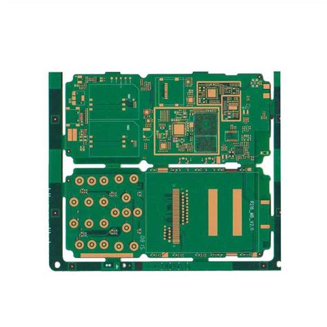
When designing metal core PCB prototypes, heat spreader configuration directly impacts thermal efficiency and long-term reliability. Start by selecting materials with high thermal conductivity, such as aluminum or copper alloys, to ensure rapid heat transfer away from high-power components. PCB manufacturing companies often recommend integrating the heat spreader into the base layer, as this minimizes thermal resistance between the heat source and the cooling medium.
To optimize performance, align the spreader’s thickness with the board’s power density—thicker spreads (1.5–3.0 mm) suit high-current applications, while thinner options reduce PCB manufacturing cost in low-to-medium power designs. Ensure the spreader’s footprint matches critical component layouts, avoiding overlaps with sensitive circuits to prevent electromagnetic interference (EMI).
Pairing the spreader with thermally conductive dielectric layers (e.g., ceramic-filled polymers) enhances heat dissipation paths. For multi-layer designs, collaborate with your PCB manufacturing business partner to verify layer stackup compatibility, as improper bonding can compromise structural integrity. Finally, validate configurations through thermal simulation tools before prototyping—this step reduces iterative costs and accelerates time-to-market for high-performance applications.
Layer Stackup for Enhanced Thermal Efficiency
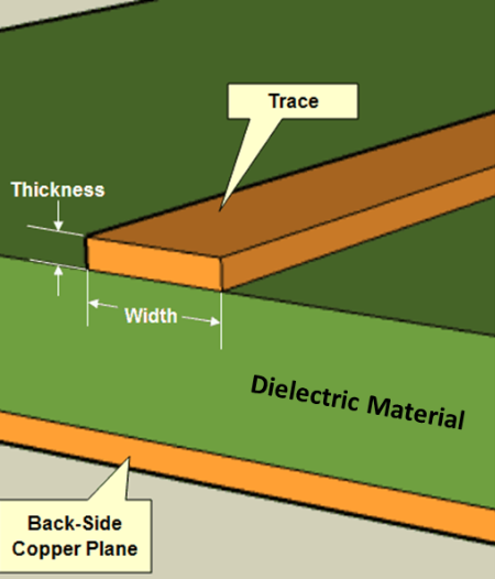
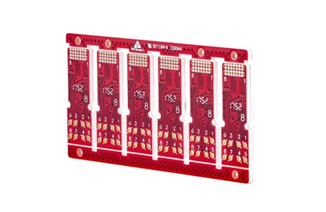
When planning your metal core PCB prototype, the layer stackup directly determines how effectively heat dissipates from high-power components. Start by positioning the metal core (typically aluminum or copper) as the base layer, acting as both a structural anchor and primary heat spreader. Above this, a thermally conductive dielectric layer bridges the circuit layers and the core, ensuring minimal thermal resistance. For optimal performance, PCB manufacturing companies often recommend keeping this dielectric material thin (0.05–0.2 mm) to accelerate heat transfer while maintaining electrical insulation.
The copper circuit layer’s thickness also plays a critical role. Thicker copper (2–6 oz) improves current-carrying capacity and distributes heat more evenly, but it raises PCB manufacturing cost due to material and processing complexities. Balance this by strategically thickening copper only in high-current zones. Incorporating thermal vias beneath heat-generating components—like LEDs or power transistors—creates vertical pathways to channel heat toward the metal core. However, avoid overcrowding vias, as this can weaken mechanical stability.
In high-frequency designs, pair your thermal strategy with EMI shielding by embedding ground planes adjacent to signal layers. This dual-purpose stackup not only manages heat but also reduces electromagnetic interference—a common challenge in PCB manufacturing business for high-power applications. Always validate your stackup with thermal simulation tools before prototyping to minimize iterative costs.
Designing Durable Metal Core PCB Prototypes
When creating durable metal core PCB prototypes, your design choices directly impact longevity and reliability in demanding applications. Start by selecting thermally stable substrates like aluminum or copper alloys, which balance heat dissipation and mechanical strength. To minimize pcb manufacturing cost, collaborate with experienced pcb manufacturing companies to optimize material thickness—thicker metal cores enhance durability but may require adjustments in layer stackup.
Ensure proper mechanical anchoring for components exposed to vibration or thermal cycling. Reinforce mounting holes with annular rings and avoid sharp corners in traces to reduce stress points. For high-power circuits, integrate EMI shielding layers into the design early to prevent signal interference, which can degrade performance over time.
Durability also hinges on thermal expansion compatibility between the metal core and dielectric layers. Mismatched coefficients can cause delamination during operation. Work with your pcb manufacturing business partner to test prototypes under accelerated aging conditions, simulating real-world thermal loads and humidity exposure.
Finally, balance pcb manufacturing precision with scalability. Tight tolerances improve reliability but may increase production complexity. Use simulation tools to validate thermal and mechanical behavior before finalizing the design, ensuring your prototype meets both performance targets and long-term operational demands.
Balancing Cost and Performance in MCPCBs
When designing metal core PCB prototypes, achieving the right equilibrium between pcb manufacturing cost and performance requires strategic decision-making. While high-performance materials like copper cores excel in thermal conductivity, they can significantly inflate expenses. Optimizing material thickness—for example, using thinner aluminum substrates where possible—reduces weight and cost without sacrificing critical heat dissipation. Partnering with experienced pcb manufacturing companies ensures access to cost-effective fabrication techniques, such as hybrid stackups that combine standard FR-4 layers with metal cores for targeted thermal management.
To minimize pcb manufacturing business overheads, prioritize designs that standardize layer counts and avoid overly complex geometries. However, never compromise on features like dielectric insulation quality or EMI shielding effectiveness, as these directly impact reliability in high-power applications. Consider prototyping with mid-tier metals (e.g., aluminum instead of copper) and validate performance before scaling. Advanced pcb manufacturing processes, such as laser-drilled vias or selective anodizing, may add upfront costs but enhance long-term durability, reducing total lifecycle expenses.
Finally, leverage simulation tools to identify over-engineered areas. For instance, adjusting heat spreader dimensions or optimizing solder mask coverage can trim material usage while maintaining thermal efficiency. By aligning design choices with both technical requirements and budgetary constraints, you ensure prototypes meet performance benchmarks without exceeding pcb manufacturing cost thresholds.
Conclusion
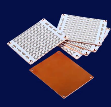
When finalizing your metal core PCB prototype design, remember that structural choices directly impact thermal performance and long-term reliability. Your collaboration with PCB manufacturing companies becomes critical at this stage—their expertise in material handling and process optimization can significantly influence PCB manufacturing cost while maintaining quality. By prioritizing heat dissipation pathways and EMI shielding integration, you create prototypes that meet both electrical and mechanical demands in high-power environments.
Effective designs require balancing copper thickness with dielectric properties—a decision that affects both PCB manufacturing business efficiency and end-product durability. When working with manufacturers, verify their capabilities in precision etching and thermal interface bonding to ensure your design intent translates accurately into physical boards. This balance becomes particularly crucial when scaling from prototypes to full production, where PCB manufacturing tolerances directly affect yield rates.
Always validate your design through thermal cycling tests before committing to mass production. This approach not only reduces iteration cycles but also builds confidence in your product’s performance under stress. Selecting a PCB manufacturing business with proven experience in metal core applications ensures you avoid common pitfalls like delamination or uneven heat distribution. Ultimately, a well-executed prototype lays the foundation for devices that excel in reliability, efficiency, and compliance with industrial standards.
FAQs
How does thermal conductivity affect PCB manufacturing costs in metal core designs?
Higher thermal conductivity materials like aluminum cores reduce long-term cooling expenses but may increase initial PCB manufacturing costs due to specialized processing. Balancing material choices with application requirements ensures cost-effective thermal management.
What factors should you prioritize when selecting PCB manufacturing companies for metal core prototypes?
Look for expertise in high-power designs, certified thermal management capabilities, and proven experience with EMI shielding integration. Reputable PCB manufacturing companies often provide material compatibility charts and design-for-manufacturing (DFM) feedback.
Can PCB manufacturing business models support low-volume metal core prototype orders?
Yes, many specialized PCB manufacturing businesses offer flexible prototyping services with rapid turnaround times. Confirm their capacity for precision etching and laser drilling to maintain structural integrity in complex layer stackups.
How does dielectric layer thickness influence PCB manufacturing cost for metal core boards?
Thinner dielectric layers improve heat transfer but require tighter process controls, potentially raising PCB manufacturing costs. Work with suppliers to optimize this parameter for your thermal efficiency and budget constraints.
Why is copper weight critical in durable metal core PCB prototypes?
Heavier copper traces (2 oz+) enhance current-carrying capacity and heat distribution, reducing failure risks in high-temperature environments. This adjustment may affect PCB manufacturing costs but significantly boosts reliability.
Ready to Optimize Your Metal Core PCB Design?
Explore tailored solutions for high-performance prototypes at https://www.andwinpcb.com/pcb-manufacturing/. Click here to connect with engineers specializing in thermal-efficient PCB manufacturing for demanding applications.

