Moto m pcb board
Understanding the Components of the Moto M PCB Board
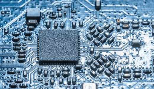
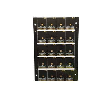
The Moto M PCB board, a critical component of the Moto M smartphone, serves as the backbone of the device, integrating various electronic components to ensure seamless functionality. Understanding the components of this printed circuit board (PCB) is essential for those interested in electronics, smartphone repair, or simply gaining insight into how modern mobile devices operate. At the heart of the Moto M PCB board lies the central processing unit (CPU), which acts as the brain of the smartphone. This microprocessor executes instructions and processes data, enabling the device to perform tasks ranging from simple calculations to complex operations. The CPU is supported by the graphics processing unit (GPU), which handles rendering images, videos, and animations, ensuring a smooth visual experience for the user.
Adjacent to the CPU and GPU, one finds the memory components, including both RAM and storage chips.
RAM, or random-access memory, provides temporary storage for data that the CPU needs to access quickly, facilitating multitasking and efficient operation. Meanwhile, the storage chips, often based on flash memory technology, retain user data, applications, and the operating system even when the device is powered off. These memory components are crucial for the overall performance and user experience of the Moto M smartphone.
In addition to processing and memory components, the Moto M PCB board houses various connectivity modules.
The Wi-Fi and Bluetooth modules enable wireless communication, allowing the device to connect to the internet and other devices without the need for physical cables. These modules are essential for modern smartphones, as they support a wide range of functionalities, from browsing the web to streaming media and transferring files. Furthermore, the cellular modem, another vital component, facilitates mobile network connectivity, enabling voice calls, text messaging, and mobile data usage.
Power management is another critical aspect of the Moto M PCB board.
The power management integrated circuit (PMIC) regulates the distribution of power throughout the device, ensuring that each component receives the appropriate voltage and current. This regulation is vital for maintaining the device’s efficiency and prolonging battery life. Additionally, the PMIC often includes charging circuitry, which manages the charging process to prevent overcharging and overheating, thereby safeguarding the battery’s health.
Audio and sensor components also play a significant role in the functionality of the Moto M PCB board.
The audio codec converts digital audio signals into analog signals and vice versa, enabling sound output through speakers and headphones as well as sound input via microphones. Meanwhile, various sensors, such as accelerometers, gyroscopes, and proximity sensors, provide the device with contextual awareness, allowing it to respond intelligently to user interactions and environmental changes.
Finally, the Moto M PCB board includes numerous passive components, such as resistors, capacitors, and inductors, which perform essential functions like filtering signals, storing energy, and controlling current flow. These components, though often overlooked, are indispensable for the stable operation of the device.
In conclusion, the Moto M PCB board is a complex assembly of various components, each playing a crucial role in the overall functionality of the smartphone.
From processing and memory to connectivity and power management, these components work in harmony to deliver a seamless user experience. Understanding the intricacies of the Moto M PCB board not only provides insight into the engineering marvels of modern smartphones but also highlights the importance of each component in ensuring the device’s performance and reliability.
How to Troubleshoot Common Issues on the Moto M PCB Board
The Moto M PCB board, a critical component of the Moto M smartphone, serves as the backbone for its electronic functions. Understanding how to troubleshoot common issues on this board can be invaluable for both technicians and enthusiasts alike. The process of diagnosing and resolving problems on the Moto M PCB board requires a methodical approach, as well as a keen understanding of the board’s layout and functions.
To begin with, it is essential to identify the symptoms of the problem.
Common issues may include the device not powering on, erratic behavior, or connectivity problems. Once the symptoms are clear, the next step is to perform a visual inspection of the PCB board. This involves carefully examining the board for any obvious signs of damage, such as burnt components, broken traces, or loose connections. Such physical damage can often be the root cause of the malfunction and may require component replacement or soldering to restore functionality.
In cases where the visual inspection does not reveal any apparent issues, it is advisable to use diagnostic tools to further investigate.
A multimeter is an indispensable tool in this regard, allowing for the measurement of voltage, current, and resistance across various components on the board. By comparing these measurements against the expected values, one can pinpoint faulty components or connections. For instance, if a particular section of the board is not receiving power, tracing the power path with a multimeter can help identify where the interruption occurs.
Moreover, software-related issues can also manifest as hardware problems.
Therefore, it is prudent to ensure that the device’s firmware is up to date and that any software glitches are addressed. Performing a factory reset or reinstalling the firmware can sometimes resolve issues that appear to be hardware-related but are actually caused by software corruption.
In addition to these steps, it is important to consider the role of environmental factors.
Excessive heat, moisture, or dust can adversely affect the performance of the PCB board. Ensuring that the device is used within its specified environmental conditions can prevent many common issues from arising. If environmental damage is suspected, cleaning the board with isopropyl alcohol and ensuring proper ventilation can mitigate some of these effects.
Furthermore, it is crucial to handle the PCB board with care during troubleshooting.
Electrostatic discharge (ESD) can damage sensitive components, so using an anti-static wrist strap and working on an ESD-safe mat is recommended. This precaution helps protect the board from additional damage during the diagnostic process.
In conclusion, troubleshooting the Moto M PCB board involves a combination of visual inspection, diagnostic testing, software checks, and environmental considerations. By systematically addressing each potential source of the problem, one can effectively identify and resolve issues, thereby restoring the device to optimal functionality. This structured approach not only aids in efficient problem-solving but also enhances one’s understanding of the intricate workings of the Moto M PCB board.
A Step-by-Step Guide to Repairing the Moto M PCB Board
Repairing the Moto M PCB board requires a meticulous approach, as it involves handling delicate electronic components. Understanding the intricacies of the printed circuit board (PCB) is crucial before embarking on the repair process. The PCB serves as the backbone of the Moto M, housing essential components and facilitating communication between them. Therefore, any malfunction can significantly impact the device’s performance. To address this, a systematic step-by-step guide is essential for ensuring a successful repair.
Initially, it is imperative to gather the necessary tools and materials.
A set of precision screwdrivers, a multimeter, soldering iron, solder, desoldering pump, and anti-static wrist strap are fundamental. Additionally, having a magnifying glass or microscope can aid in examining small components. Once equipped, the next step involves preparing a clean, static-free workspace to prevent any damage to the sensitive electronic parts.
Before proceeding with the repair, it is essential to diagnose the issue accurately.
This involves inspecting the PCB for visible signs of damage, such as burnt components, broken traces, or loose connections. Utilizing a multimeter can help in testing the continuity of the circuits and identifying faulty components. Once the problematic area is identified, the repair process can commence.
The first step in the actual repair is to carefully disassemble the Moto M.
This involves removing the back cover, battery, and any screws securing the PCB. It is crucial to keep track of all screws and components to ensure a smooth reassembly later. With the PCB exposed, the next task is to address the identified issue. If a component needs replacement, it is necessary to desolder the faulty part using a soldering iron and desoldering pump. This requires precision to avoid damaging the surrounding components or the PCB itself.
After removing the defective component, the next step is to solder the new component in place.
This involves heating the soldering iron to the appropriate temperature and carefully applying solder to secure the new part. It is vital to ensure that the solder joints are clean and free of any bridges that could cause short circuits. Once the new component is securely in place, it is advisable to recheck the connections with a multimeter to confirm that the issue has been resolved.
Following the repair, reassembling the Moto M is the final step.
This involves carefully placing the PCB back into its housing, ensuring that all connectors are properly aligned and secured. Reattaching the battery and back cover, along with any screws, completes the reassembly process. It is crucial to handle all components with care to avoid introducing new issues during this stage.
In conclusion, repairing the Moto M PCB board is a task that demands attention to detail and a methodical approach. By following a structured process, from diagnosing the issue to reassembling the device, one can effectively address and resolve PCB-related problems. This not only restores the functionality of the Moto M but also extends its lifespan, providing continued value to the user. Through careful execution of each step, the repair process can be both successful and rewarding.
Enhancing Performance: Upgrading the Moto M PCB Board
The Moto M smartphone, known for its sleek design and robust performance, has garnered a significant user base since its release. However, as technology advances, so does the need for enhanced performance and efficiency. One of the most effective ways to achieve this is by upgrading the Moto M’s printed circuit board (PCB). The PCB is the backbone of any electronic device, serving as the platform that connects and supports various components. By focusing on upgrading the Moto M PCB board, users can experience improved functionality and longevity of their devices.
To begin with, understanding the role of the PCB in the Moto M is crucial.
The PCB is responsible for housing the smartphone’s essential components, such as the processor, memory, and connectivity modules. It ensures that these components communicate effectively, thereby facilitating the device’s overall performance. As technology evolves, newer components with enhanced capabilities become available, necessitating a PCB upgrade to accommodate these advancements. By upgrading the PCB, users can integrate more powerful processors and larger memory modules, which can significantly boost the device’s speed and multitasking capabilities.
Moreover, upgrading the Moto M PCB board can lead to improved energy efficiency.
Modern PCBs are designed with advanced materials and technologies that reduce power consumption. This is particularly important for smartphones, as battery life is a critical concern for users. By incorporating a more efficient PCB, the Moto M can manage power distribution more effectively, leading to longer battery life and reduced energy waste. This not only enhances user experience but also contributes to environmental sustainability by minimizing the device’s carbon footprint.
In addition to performance and efficiency, upgrading the PCB can also enhance the Moto M’s connectivity features.
As wireless technologies continue to evolve, newer standards such as 5G and Wi-Fi 6 are becoming increasingly prevalent. A PCB upgrade can facilitate the integration of these advanced connectivity options, allowing users to enjoy faster internet speeds and more reliable connections. This is particularly beneficial for activities such as streaming high-definition content, online gaming, and video conferencing, where stable and fast connectivity is essential.
Furthermore, upgrading the Moto M PCB board can improve the device’s thermal management.
As smartphones become more powerful, they generate more heat, which can affect performance and longevity. Modern PCBs are designed with better heat dissipation mechanisms, ensuring that the device remains cool even during intensive tasks. This not only prevents overheating but also extends the lifespan of the device by reducing wear and tear on its components.
In conclusion, upgrading the Moto M PCB board offers a multitude of benefits that enhance the device’s performance, efficiency, connectivity, and thermal management. As technology continues to advance, staying up-to-date with the latest PCB innovations is essential for maximizing the potential of the Moto M smartphone. By investing in a PCB upgrade, users can ensure that their devices remain competitive in an ever-evolving technological landscape, providing them with a superior user experience and a longer-lasting device. As such, the importance of upgrading the Moto M PCB board cannot be overstated, as it is a key factor in unlocking the full capabilities of this popular smartphone.