Offline programming of SMT placement machine
Offline programming refers to the work of compiling SMT placement programs on a computer using offline programming software and PCB CAD design files. Offline programming can save online programming time, thereby reducing the downtime of the entire PCBA processing and improving the utilization rate of equipment. Offline programming software
Generally consists of two parts: CAD conversion software and automatic programming and optimization software.
Offline programming steps: PCB program data editing – automatic programming optimization and editing – input data into the device – edit the optimized product program on the placement machine – proofread and back up the placement program.
1.PCB program data editing
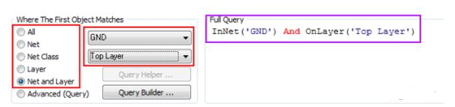
There are three methods for PCB program data editing: CAD conversion, using the coordinate file generated by the placement machine self-learning programming, and using the scanner to generate the coordinate data of the component. Among them, CAD conversion is the simplest and most accurate.
1.CAD data conversion
(1) CAD conversion project.
●Component name for each step: ●Description:
●X, y coordinates and rotation angle Θ for each step ●mm/inch conversion;
●Coordinate direction conversion; ●Angle Θ conversion;
●Ratio; ●Origin correction value
(2) CAD conversion operation steps
●Call out the text file of surface mount component coordinates.
When the file format does not meet the requirements, call out the text file from Excel: select the delimiter in the pop-up text import wizard, click the “Next” button, select “Space”, click the “Next” button, select “Text”, click the “Finish” button to display the file in Excel; use the delete, cut and paste tools to adjust the file to the required format.
●Open the CAD conversion software.
●Select the CAD data format.
If you create a new file. A blank Format Edit window will pop up; if you edit an existing file, a format edit window with data will pop up, and then you can modify and edit the pop-up format.
●Compare the text file and enter the data to be converted.
●Convert after saving.
2.Use the coordinate program generated by the self-learning programming of the SMT placement machine, and convert and edit it through the software.
When there is no CAD text file of the coordinates of the surface mounted components, the patch coordinates generated by the self-learning programming of the SMT placement machine can be used, and then converted and edited through the software (the software needs to have a text conversion function).
1.Conversion and editing conditions.
● An unprinted PCB is required;
● A surface mounted component list and assembly drawing are required;
● A USB flash drive for backup.
2.Operation steps.
●Use the SMT placement machine self-learning programming to input the component name, X, Y coordinates and rotation angle θ. The remaining parameters can be generated during automatic programming and optimization (if the placement machine itself is equipped with optimization software, it can be optimized directly on the placement machine, otherwise follow the steps below);
●Back up the coordinate program generated by the placement machine self-learning programming to a USB flash drive;
●Copy the coordinate program generated by the placement machine self-learning programming to the CAD conversion software;
●Convert the coordinate program generated by the placement machine self-learning programming into a text file;
●Format the text file;
●Convert.
3.Use a scanner to generate component coordinate data (coordinate conversion software must be available)
(1) Place the PCB in the appropriate position of the scanner for scanning;
(2) Generate a PCB coordinate file through the coordinate conversion software;
(3) Perform CAD conversion as described in (1) above.