PCB Basics – Types of PCBs
First, single-sided (Single-Sided Boards)
As we just mentioned, on the most basic PCB, parts are concentrated on one side, and wires are on the other side. Because the wires only appear on one side, we call this type of PCB a single-sided board. Because a single panel has many strict restrictions on the design circuit (because there is only one side, the wiring can not be crossed and must be routed around its own path), only the early circuits use this kind of board.
Second, double-sided board (Double-Sided Boards)
There are wirings on both sides of this board. However, to use both wires, proper circuit connections must be made between the two sides. This “bridge” between circuits is called a via. The via hole is on the PCB, filled with or coated with a metal hole, and it can be connected to the wires on both sides. Because the double-sided board is twice as large as a single board, and because the wires can be interleaved (wrap around to the other side), it is more suitable for use on circuits that are more complex than a single board.
Third, Multi-Layer Boards (Multi-Layer Boards)
In order to increase the area that can be wired, the multilayer board uses more single or double-sided wiring boards. Multilayer boards use several double-sided boards and are laminated (inserted) after placing an insulating layer between each board. The number of layers
on the board represents several layers of independent wiring layers.
Usually, the number of layers is even, and includes the outermost two layers. Most motherboards have a 4- to 8-layer structure, but it is technically possible to implement nearly 100-layer PCB boards. Large-scale supercomputers mostly use quite multi-layered motherboards, but since these types of computers can already be replaced by clusters of many ordinary computers, super-multi-layer boards have gradually disappeared.
used. Because the layers in the PCB are tightly integrated, it is generally not easy to see the actual number, but if you look closely at the motherboard, you may be able to see it.
The vias we just mentioned, if applied on double-sided boards, must be broken through the board.
However, in a multi-layer board, if you only want to connect some of the wires, the vias may waste some of the other board space. Buried vias and blind vias techniques can avoid this problem because they penetrate only a few layers. Blind vias connect several layers of internal PCB to surface PCB without penetrating the entire board. Buried holes only connect the internal PCB, so the light is not visible from the surface.
In a multilayer PCB, the entire layer is directly connected to the ground and the power supply. So we classify each layer as Signal, Power, or Ground. If the parts on the PCB require different power supplies, this type of PCB usually has more than two layers of power and wire layers.
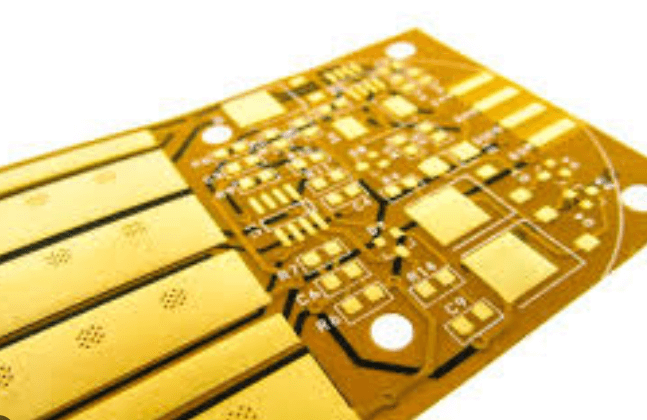
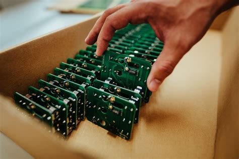
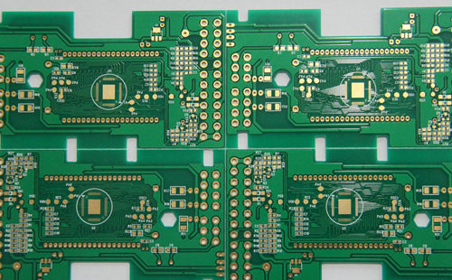
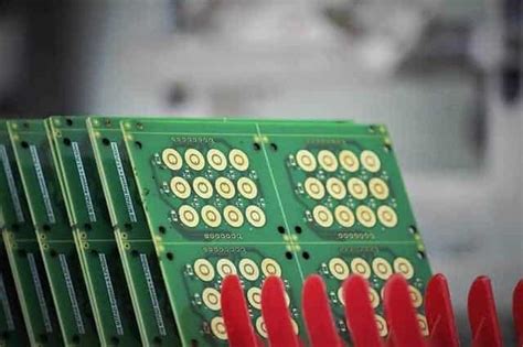
Why are most PCB boards green?
The answer to this question (why are the boards mostly green?) is the following:
Viewpoint 1. Generally speaking, the entire electronic board product must go through the system board and post process.
There are several processes in the boarding process that go through the yellow room. The visual effect of the green room in the yellow room is better. But this is not the main thing.
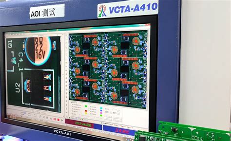
During SMT soldering, the upper tin and posts and the final AOI calibration are required. These processes all require optical alignment and calibration. The green background has a better recognition effect on the instrument.
Point of view 2. Common red, yellow, green, blue and black.
Due to process problems, many lines of inspection are still depending on the worker’s eyes (of course, most of them use flying probes for testing now). This is a very tiring job. Green is relatively least to hurt the eyes.
So most use green.
Point of view 3, blue and black are because they are doped with cobalt and carbon, respectively, have a certain degree of conductivity, so there is a risk of short circuit, green PCB is more environmentally friendly, will not release toxic gases when used in high temperature environment.
Viewpoint 4, from about 2007, people began to pay attention to the color of the PCB board, mainly because the high-end board of Asustek MSI these first-tier manufacturers have adopted a black PCB board color design, so people slowly think that PCB color Black is definitely high-end.
Since then, more and more manufacturers have begun to use black PCB coating – it can be said that a strange reason has caused such an inexplicable phenomenon.
No one has ever said that the PCB color is black to represent the quality of the motherboard. It is entirely due to the misleading product identification caused by the first-tier brands using black to identify product positioning. It is true that black PCBs are indeed capable of demonstrating their own technological capabilities, because black PCBs are the least visible traces. Therefore, both design and after-sales services will be subject to unprecedented cost pressure, while the technically strong board manufacturers use black PCBs. Color tone is not because of the black can enhance the performance of the motherboard, from a rational analysis point of view know that color alone can not improve the performance of the card.
Point of view 5, no reason, but it has been used.