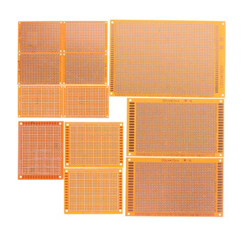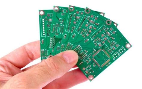
PCB board integrity and solutions
The unexpected noise voltage signal generated by the mutual interference of electromagnetic fields between signals is called signal crosstalk. Crosstalk exceeding a certain value may cause circuit malfunction and cause the system to fail to work properly. Solving the crosstalk problem can be considered from the following aspects:
The conversion rate is usually selected when the device is selected.
While meeting the design specifications, try to choose slow devices and avoid mixing different types of signals, because fast-changing signals have potential crosstalk risks to slow-changing signals.
Shielding measures provide grounding for high-speed signals, which is an effective way to solve the crosstalk problem.
However, grounding will increase the amount of wiring, making the originally limited wiring area more crowded. In addition, the spacing between ground points on the ground wire is critical for the ground wire shielding to achieve the desired purpose, which is generally less than twice the length of the signal change edge. At the same time, the ground wire will also increase the distributed capacitance of the signal, increase the transmission line impedance, and slow down the signal edge.

Routing Reasonable setting of wiring layers and wiring spacing, reducing the length of parallel signals, shortening the spacing between signal layers and plane layers, increasing the spacing between signal lines, and reducing the length of parallel signal lines (within the critical length range) can effectively reduce crosstalk.
Setting different wiring layers for signals of different rates and reasonably setting plane layers are also good ways to solve crosstalk.
Impedance matching If the impedance of the near-end or far-end terminal of the transmission line matches the impedance of the transmission line, the amplitude of crosstalk can also be greatly reduced. The purpose of crosstalk analysis is to quickly discover, locate and solve crosstalk problems in PCB implementation.
In general simulation tools and environments, simulation analysis is independent of the PCB board wiring environment.
After wiring, crosstalk analysis is performed to obtain a crosstalk analysis report, derive new wiring rules and re-wiring, and then analyze and correct. This design is repeated more. Through simulation analysis, it can be seen that the actual crosstalk results are different and the gap is large. Therefore, a good tool should not only be able to analyze crosstalk, but also be able to apply crosstalk rules for wiring.
In addition, general wiring tools are limited to physical rule-driven, and the wiring to control crosstalk can only be constrained by setting physical rules such as line width and line spacing, as well as the maximum parallel routing length. The use of signal integrity analysis and design tool set ICX can support true electrical rule-driven wiring. Its simulation analysis and wiring are completed in one environment. During simulation, electrical rules and physical rules can be set. Signal integrity elements such as overshoot and crosstalk are automatically calculated while wiring, and the wiring is automatically corrected according to the calculation results. This kind of wiring is fast and truly meets the actual electrical performance requirements.
High-speed PCB design rules are usually divided into two types: physical rules and electrical rules.
The so-called physical rules refer to certain design rules based on physical dimensions specified by design engineers, such as line width of 4Mi1, spacing between lines of 4Mi1, parallel routing length of 4Mi1, etc. Electrical rules refer to design rules related to electrical characteristics or electrical performance, such as wiring delay control between Ins and 2ns, the total amount of crosstalk on a certain PCB line is less than 70mV, etc. After the physical rules and electrical rules are clearly defined, high-speed wiring can be further explored. The high-speed routers based on physical rules (driven by physical rules) on the market include AutoActive RE router, CCT router, B1azeRouter router and Router Editor router. In fact, these routers are all physical rule-driven automatic routers, that is, these routers can only automatically meet the physical size requirements specified by the design engineer, and cannot be directly driven by the physical size requirements of high-speed electrical, and cannot be directly driven by high-speed electrical rules.
High-speed routers directly driven by electrical rules are very important for ensuring the signal integrity of high-speed designs.
Design engineers always get electrical rules first and design specifications are also electrical rules. In other words, our designs must ultimately meet electrical rules rather than physical rules. The final physical design realization that meets the electrical rule requirements of the design is the most essential. Physical rules are just a conversion of electrical rules by component manufacturers or design engineers themselves. We always expect this conversion to be equal and one-to-one. But the actual situation is not the case. Take the use of LVDS chips to complete high-speed (up to 777.76Mbps) and long-distance (up to loom) data transmission as an example. Since the signal swing of LVDS technology is 3500, the usual design specifications always require that the total crosstalk value on the signal line should be less than or equal to 20% of the signal swing,
that is, the total amount of crosstalk is 350mV X20%=700 at most. This is the electrical rule, where the percentage of 20% depends on the noise tolerance of LVDS, which can be obtained from the reference manual. For IS_Synthesizer, as long as the design engineer specifies the crosstalk value on the LVDS signal line, it can automatically adjust and refine it during wiring to ensure that the electrical performance requirements are met. During the wiring process, it will automatically consider the impact of all surrounding signal lines on the LVDS signal.
For the router driven by physical rules, some hypothetical analysis and considerations are needed first.
Design engineers always think that the crosstalk between signals depends only on the length of the parallel lines between parallel signals, so some hypothetical analysis can be done in the front-end environment of high-speed circuit design. For example, it can be assumed that the length of the parallel lines is 2.5mil, and then the crosstalk between them can be analyzed.
This value may not be 70mV, but the length of the parallel lines can be further adjusted based on the conclusions obtained.
If the length of the parallel lines is a certain value such as 7mi1, the crosstalk value between the signals is basically 70mV, then the design engineer believes that as long as the length of the differential line pair parallel lines is controlled within the range of 7mi1, such electrical characteristics requirements can be met (the signal crosstalk value is controlled within 70mV). Therefore, in the actual physical PCB layout and routing, the design engineer obtains such a physical rule for high-speed PCB design, and conventional high-speed routers can ensure that such physical size requirements are met.
There are two problems here: First, the conversion of rules is not equivalent.
First, the crosstalk between signals is not only determined by the length of the parallel signal routing, but also depends on the flow direction of the signal, the location of the parallel line segments, and whether there is a match, etc. These factors may be difficult to predict, and even impossible to fully consider before the actual physical implementation.
Therefore, after such a conversion, it is not possible to ensure that the original electrical rules can be met while meeting these physical rules.
This is also an important reason why the PCB system still cannot work properly when the above-mentioned high-speed routers meet the rules. Secondly, it is almost impossible to consider multiple influences at the same time when these rules are converted. For example, it is difficult to consider the influence of all related signal lines around when considering signal crosstalk. These two aspects determine that the high-speed router based on physical rules will have great problems in the design of high-speed and high-complexity PCB systems, while the high-speed PCB router driven by electrical rules can better solve this problem.