PCB Copper Pour Handling: Best Practices and Practical Experience
Introduction
Printed Circuit Board (PCB) design involves numerous critical steps, one of which is the proper handling of copper pour (also known as copper fill or copper plating). Copper pouring is essential for improving signal integrity, thermal management, and electromagnetic compatibility (EMC). However, improper copper pour techniques can lead to manufacturing defects, signal interference, and even board failure. This article explores best practices, common challenges, and practical experience in PCB copper pour processing.
1. Understanding Copper Pour in PCB Design
Copper pour refers to the process of filling unused areas of a PCB with solid or hatched copper. This technique serves multiple purposes:
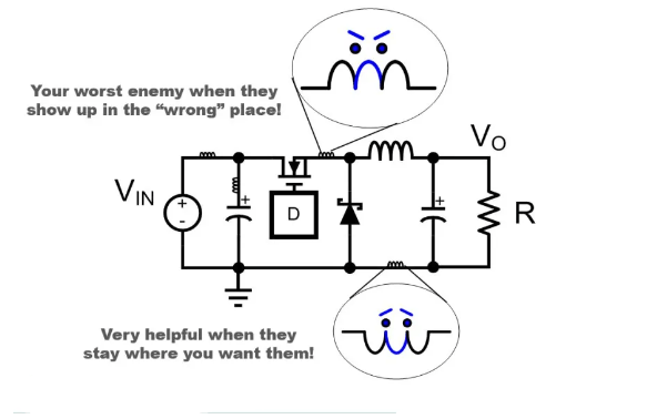
- Grounding and Shielding: Copper pour connected to ground (GND) helps reduce electromagnetic interference (EMI) by providing a low-impedance return path.
- Thermal Management: Large copper areas dissipate heat more efficiently, benefiting high-power components.
- Reducing Etching Time: Less copper to etch means faster fabrication and lower production costs.
- Improving Mechanical Stability: Copper reinforcement prevents warping and enhances durability.
However, improper copper pour can introduce problems like unintended short circuits, parasitic capacitance, and manufacturing difficulties.
2. Types of Copper Pour
There are two primary methods of applying copper pour:
2.1 Solid Copper Pour
- Advantages:
- Excellent thermal and electrical conductivity.
- Better EMI shielding due to continuous copper.
- Disadvantages:
- Can cause uneven copper distribution, leading to warping during reflow soldering.
- May increase parasitic capacitance in high-frequency circuits.
2.2 Hatched Copper Pour (Grid Copper)
- Advantages:
- Reduces thermal stress and warping.
- Minimizes parasitic capacitance in RF and high-speed designs.
- Disadvantages:
- Lower conductivity compared to solid copper.
- Less effective for EMI shielding.
3. Best Practices for Copper Pour Implementation
3.1 Proper Grounding Strategy
- Always connect copper pour to a stable ground plane to avoid floating copper, which can act as an antenna and introduce noise.
- Use multiple vias for grounding to ensure low impedance.
3.2 Thermal Relief Pads
- For through-hole and SMD components, thermal relief connections prevent excessive heat dissipation during soldering, improving manufacturability.
- Avoid direct solid copper connections to pads, as they can cause soldering defects (e.g., tombstoning).
3.3 Clearance and Isolation Rules
- Maintain proper clearance between copper pour and signal traces to prevent short circuits.
- Follow IPC standards for minimum spacing (typically 0.2mm–0.3mm for standard PCBs).
- Isolate high-voltage traces to prevent arcing.
3.4 Avoiding Copper Islands (Dead Copper)
- Unconnected copper areas (islands) can accumulate charge and cause EMI issues.
- Use design rule checks (DRC) to detect and remove isolated copper.
3.5 Copper Thickness Considerations
- Standard PCBs use 1oz (35µm) copper, but high-current designs may require 2oz or thicker copper.
- Thicker copper improves current handling but may increase fabrication costs.
4. Common Copper Pour Issues and Solutions
4.1 EMI and Signal Integrity Problems
- Problem: Poorly placed copper pour can introduce crosstalk and ground loops.
- Solution:
- Use a solid ground plane under high-speed signals.
- Avoid splitting ground planes unnecessarily.
4.2 Copper Peeling During Manufacturing
- Problem: Thin copper traces or improper adhesion can cause peeling.
- Solution:
- Ensure proper surface finish (e.g., HASL, ENIG).
- Use teardrops at trace-to-pad transitions for reinforcement.
4.3 Warping Due to Uneven Copper Distribution
- Problem: Asymmetric copper layers can cause PCB bending.
- Solution:
- Balance copper distribution across layers.
- Use hatched copper in large empty areas.
5. Advanced Techniques for High-Speed and RF PCBs
5.1 Controlled Impedance with Copper Pour
- In RF designs, copper pour affects trace impedance.
- Use simulation tools (e.g., Ansys HFSS, Altium’s field solver) to model impedance impact.
5.2 Copper Pour in Multilayer PCBs
- Inner layers should have consistent copper pour to maintain structural integrity.
- Avoid excessive void areas to prevent lamination issues.
5.3 Copper Thieving (for Even Plating)
- In high-density PCBs, copper thieving (adding small dummy copper shapes) ensures uniform electroplating.
6. Practical Tips from Industry Experience
- For High-Current PCBs: Use thick copper (2oz+) and multiple vias for current sharing.
- For High-Frequency PCBs: Minimize copper pour under sensitive analog traces to reduce parasitic capacitance.
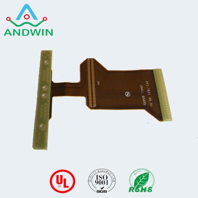
- For Flexible PCBs: Avoid solid copper in bending areas to prevent cracking.
7. Conclusion
Proper copper pour handling is crucial for PCB performance, manufacturability, and reliability. By following best practices—such as proper grounding, thermal relief, and clearance management—designers can avoid common pitfalls. Whether working on high-speed digital, RF, or power electronics PCBs, optimizing copper pour techniques ensures better signal integrity, thermal performance, and EMI compliance.
By applying these lessons from real-world PCB design, engineers can achieve robust and high-performance circuit layouts efficiently.