pcb impedance control formulas and resources

impedance control PCB

impedance control PCB

  • 1 Layer: 1-28 layers

  • 2 Sample Order: Welcome

  • 3 Surface Finished: HASL/HASL Lead Free/Immersion Gold/Immersion Silver

  • 4 Solder Color: Green/ Blue/ Red/Yellow/Black/White

  • 5 Silkscreen Color: Black/White

  • 6 Service: PCB/ PCB Assembly/ PCB Clone

  • 7 Certification: UL/ISO9001/ROHS

  • 8 Ways Of Shipment: DHL/EMS/USP/TNT/FEDEX

  • 9 Profile: Routing/ V-CUT/Beveling

  • 10 Package: Vacuum Package

Description

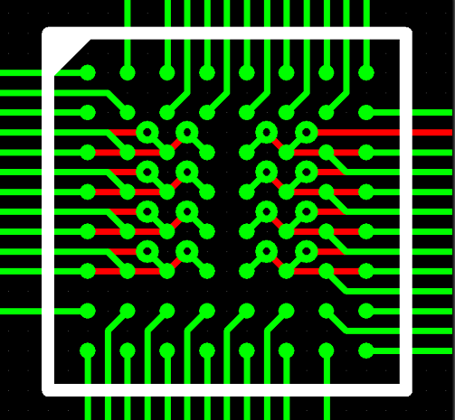
  1. What is the impedance control or a controlled impedance?

Impedance is the result of the interaction between the resistance and reactance in a circuit and expressed in Ohms. Impedance is an AC characteristic, which means it is related to frequency. A controlled impedance is important to maintain signal integrity, especially for high-frequency products.

Taconic TLX

When to Use Controlled Impedance

When a signal must have a particular impedance in order to function properly, controlled impedance should be used. In high frequency applications matching the impedance of PCB traces is important in maintaining data integrity and signal clarity. If the impedance of the PCB trace connecting two components does not match the components’ characteristic impedance, there may be increased switching times within the device or the circuit. There may also be random errors.

rigid flex pcb

Clearing Up Trace Impedance Calculators and Formulas

While it might not be obvious to the casual or to those who think the mathematics underlying PCB design is largely settled, there is plenty of disagreement regarding the right formula to calculate trace impedance. This disagreement extends to online trace impedance calculators, and designers should make themselves aware of the limitations of these tools.

PCB AOI

Applications of Controlled Impedance

Controlled Impedance should be considered for PCBs used in fast digital applications such as:

  • – Telecommunications

  • – Computing 100MHz and above

  • – High Quality Analog Video

  • – Signal Processing

  • – RF Communication

Testing the PCB

Most controlled impedance PCBs undergo 100% testing. However, it is not uncommon for the actual PCB traces to be inaccessible for testing. In addition, traces may be too short for accurate measurement and may well include branches and vias which would also make exact impedance measurements difficult. Adding extra pads and vias for test purposes would affect performance and occupy board space. PCB testing is therefore normally performed, not on the PCB itself, but on one or two test coupons integrated into the PCB panel. The coupon is of the same layer and trace construction as the main PCB and includes traces with precisely the same impedance as those on the PCB, so testing the coupon affords a high degree of confidence that the board impedances will be correct.

Repair of Printed circuit board

About Andwin Circuits

Andwin Circuits as a industry leading of PCB manufacturer since 2003.

Specializing in multilayer PCB, Rigid flex PCBHDI PCB, controlled impedance PCB and Radio Frequency circuit, from quick turn prototype to mass products.

Similar Posts

  • |

    Types of flex pcb

    1. Single-sided Kapton flex PCB: This type of flex PCB has a single layer of copper and Kapton material. 2. Double-sided Kapton flex PCB: This type of flex PCB has two layers of copper and Kapton material, with vias connecting the two layers. 3. Multi-layer Kapton flex PCB: This type of flex PCB has multiple…

  • |

    Thermal pad pcbox

    PCBox is a company that specializes in the distribution of electronic components and products.They offer a wide range of thermal pads that are designed to provide thermal management solutions for various electronic applications. These thermal pads are made of high-quality materials such as silicone, graphite, and ceramic,and are available in different sizes, thicknesses, and thermal…

  • |

    Rogers pcb 5880

    It is a ceramic-filled PTFE composite that belongs to the RO5800 series of PCB materials from Rogers Corporation. Rogers PCB 5880 has excellent electrical properties, low loss, and high thermal conductivity, making it suitable for high-frequency and high-power applications. Rogers 5880 has a dielectric constant of 2.2 and a dissipation factor of 0.0009 at 10 GHz,…

  • |

    Rogers pcb high frequency

    Rogers PCB (Printed Circuit Board) is a type of high-frequency PCB that is designed to operate at high frequencies, typically above 1 GHz. Rogers PCBs are made from a specialized material called Rogers substrate, which is a high-performance laminate material that has excellent electrical properties, such as low dielectric loss and high thermal stability. Rogers…

  • |

    High speed pcb

    High speed PCB manufacturing What is High speed PCB? High-speed PCB is a kind of PCB board manufactured with high-speed PCB material,which has the characteristics of high speed, high reliability, low delay,large capacity, and high bandwidth. In the 1990s digital signaling in electronics in 100 Mhz range was “high speed”. Chips and computer performance have…