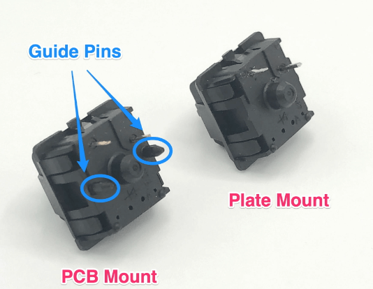
Pcb mount
Designing Efficient PCB Mounts for High-Density Applications
Designing efficient PCB mounts for high-density applications requires a meticulous approach to ensure both functionality and reliability. As electronic devices continue to shrink in size while increasing in complexity, the need for effective PCB mounting solutions becomes paramount. The primary objective is to secure the printed circuit board (PCB) within the device, ensuring stability and minimizing the risk of damage due to mechanical stress or environmental factors.
To begin with, understanding the specific requirements of the application is crucial.
High-density applications often involve compact spaces where multiple components are closely packed. This necessitates a design that maximizes space utilization without compromising the integrity of the PCB. One effective strategy is to employ surface-mount technology (SMT), which allows components to be mounted directly onto the surface of the PCB, thereby saving space and reducing the overall footprint of the device.
Moreover, the choice of materials for PCB mounts plays a significant role in the overall performance and durability of the device.
Materials such as polycarbonate, nylon, and various metal alloys are commonly used due to their strength, thermal stability, and resistance to environmental factors. The selection of the appropriate material depends on the specific operating conditions, including temperature ranges, exposure to moisture, and potential mechanical stresses.
In addition to material selection, the design of the mounting mechanism itself is critical.
Various mounting techniques, such as standoffs, clips, and screws, offer different advantages and limitations. For instance, standoffs provide a simple and effective way to elevate the PCB, allowing for better airflow and heat dissipation. Clips, on the other hand, offer a tool-less solution that can simplify assembly and maintenance processes. Screws provide a secure and robust attachment but may require additional space and tools for installation.
Thermal management is another key consideration in high-density applications.
As electronic components generate heat during operation, efficient heat dissipation becomes essential to prevent overheating and ensure optimal performance. Incorporating heat sinks, thermal vias, and proper ventilation into the PCB mount design can significantly enhance thermal management. Additionally, using materials with high thermal conductivity can help in dissipating heat more effectively.
Furthermore, the mechanical stability of the PCB mount must be ensured to withstand various stresses during operation.
This includes vibrations, shocks, and potential impacts that the device may encounter in its operating environment. Conducting thorough mechanical testing and simulations during the design phase can help identify potential weaknesses and allow for necessary reinforcements. Employing techniques such as finite element analysis (FEA) can provide valuable insights into the stress distribution and deformation of the PCB mount under different conditions.
Lastly, considering the ease of assembly and maintenance is essential for practical implementation.
A well-designed PCB mount should facilitate straightforward assembly processes, reducing the time and effort required for installation. Additionally, it should allow for easy access to the PCB for maintenance and repairs, minimizing downtime and ensuring the longevity of the device.
In conclusion, designing efficient PCB mounts for high-density applications involves a comprehensive approach that addresses various factors, including space utilization, material selection, mounting techniques, thermal management, mechanical stability, and ease of assembly. By carefully considering these aspects, engineers can develop robust and reliable PCB mounting solutions that meet the demands of modern electronic devices.
Innovative Materials for Durable PCB Mounts
Printed Circuit Boards (PCBs) are the backbone of modern electronic devices, serving as the platform upon which electronic components are mounted and interconnected. The durability and reliability of these boards are paramount, especially in applications where failure is not an option. One critical aspect that contributes to the longevity and performance of PCBs is the material used for their mounts. Innovative materials for durable PCB mounts have been developed to address the challenges posed by various environmental and operational conditions.
Traditionally, PCB mounts were made from materials such as metal and plastic.
While these materials have served their purpose, they often fall short in extreme conditions, such as high temperatures, corrosive environments, and mechanical stress. To overcome these limitations, researchers and engineers have turned to advanced materials that offer superior properties. One such material is high-performance thermoplastics, which provide excellent mechanical strength, thermal stability, and chemical resistance. These properties make thermoplastics ideal for applications in harsh environments, such as aerospace, automotive, and industrial electronics.
In addition to thermoplastics, composite materials have gained traction in the field of PCB mounts.
Composites, which are made by combining two or more distinct materials, offer a unique combination of properties that can be tailored to specific requirements. For instance, carbon fiber-reinforced polymers (CFRPs) are known for their high strength-to-weight ratio, making them suitable for applications where weight reduction is crucial without compromising structural integrity. Moreover, CFRPs exhibit excellent thermal conductivity, which helps in dissipating heat generated by electronic components, thereby enhancing the overall performance and reliability of the PCB.
Another innovative material that has shown promise for durable PCB mounts is liquid crystal polymer (LCP).
LCPs are a class of high-performance polymers that possess exceptional mechanical properties, low moisture absorption, and excellent dimensional stability. These characteristics make LCPs particularly suitable for high-frequency applications, such as telecommunications and microwave circuits, where signal integrity is of utmost importance. Furthermore, LCPs can be processed using conventional injection molding techniques, making them a cost-effective solution for mass production.
Ceramic materials have also emerged as a viable option for PCB mounts, especially in applications that demand high thermal and electrical insulation.
Ceramics, such as alumina and aluminum nitride, offer excellent thermal conductivity and can withstand high temperatures without degrading. This makes them ideal for use in power electronics and LED lighting, where efficient heat dissipation is critical to prevent overheating and ensure long-term reliability. Additionally, ceramics are inherently resistant to corrosion and wear, further enhancing their suitability for demanding environments.
As the demand for more robust and reliable electronic devices continues to grow, the development of innovative materials for durable PCB mounts will play a crucial role in meeting these requirements. By leveraging the unique properties of advanced thermoplastics, composites, liquid crystal polymers, and ceramics, engineers can design PCB mounts that not only withstand harsh conditions but also enhance the overall performance of electronic systems. Consequently, the adoption of these materials will lead to more durable and reliable electronic devices, ultimately benefiting a wide range of industries and applications.
Step-by-Step Guide to Installing PCB Mounts
Installing PCB mounts is a critical step in the assembly of electronic devices, ensuring that printed circuit boards (PCBs) are securely and accurately positioned within their enclosures. This process, while seemingly straightforward, requires meticulous attention to detail to avoid potential issues that could compromise the functionality and reliability of the final product. To assist you in achieving a successful installation, this guide will walk you through the essential steps involved in mounting PCBs.
To begin with, it is imperative to gather all necessary tools and materials.
These typically include the PCB itself, mounting hardware such as screws, standoffs, or clips, and appropriate tools like screwdrivers, pliers, and possibly a torque wrench. Ensuring that you have all components at hand before starting the installation process can save time and prevent interruptions.
Next, carefully inspect the PCB and the enclosure to identify the designated mounting points.
These points are usually marked by holes or slots on the PCB and corresponding features in the enclosure. It is crucial to verify that these points align correctly, as misalignment can lead to mechanical stress on the PCB, potentially causing damage to the board or its components.
Once the alignment is confirmed, proceed to attach the standoffs or spacers to the PCB.
Standoffs serve to elevate the PCB from the enclosure, providing necessary clearance for components and ensuring proper airflow. When selecting standoffs, consider the material and height to match the specific requirements of your application. Metal standoffs offer durability and conductivity, while plastic standoffs provide electrical insulation.
With the standoffs in place, position the PCB within the enclosure, ensuring that it sits flush against the mounting points.
At this stage, it is essential to handle the PCB with care to avoid static discharge, which can damage sensitive electronic components. Using an anti-static wrist strap or mat can help mitigate this risk.
Following the placement of the PCB, secure it using the appropriate screws or clips.
When tightening screws, apply even pressure and avoid over-tightening, as this can strip the threads or crack the PCB. If using a torque wrench, adhere to the manufacturer’s recommended torque settings to achieve optimal fastening without causing damage.
After securing the PCB, conduct a thorough inspection to ensure that all connections are firm and that the board is stable within the enclosure.
Check for any signs of stress or misalignment, and make any necessary adjustments. Additionally, verify that there is adequate clearance around the PCB to prevent short circuits or interference with other components.
Finally, perform a functional test of the assembled device to confirm that the PCB is operating correctly.
This step is crucial to identify any issues that may have arisen during the installation process. If any problems are detected, re-examine the mounting points and connections to diagnose and rectify the issue.
In conclusion, installing PCB mounts is a fundamental aspect of electronic device assembly that demands precision and care. By following these step-by-step instructions, you can ensure that your PCBs are securely and accurately mounted, thereby enhancing the reliability and performance of your electronic products. Through careful preparation, alignment, and inspection, you can achieve a successful installation that meets the highest standards of quality and functionality.
Common Mistakes to Avoid When Using PCB Mounts
When working with PCB mounts, it is crucial to be aware of common mistakes that can compromise the integrity and functionality of your electronic projects. One frequent error is the improper selection of PCB mount types. Different applications require specific mounts, and choosing the wrong type can lead to mechanical failures or electrical issues. For instance, using a mount designed for lightweight applications in a high-stress environment can result in the mount breaking or the PCB becoming dislodged. Therefore, it is essential to thoroughly understand the requirements of your project and select mounts that are designed to meet those needs.
Another common mistake is neglecting to consider the thermal management of the PCB.
Electronic components generate heat, and if this heat is not adequately dissipated, it can lead to overheating and potential damage to the components. When using PCB mounts, it is important to ensure that there is sufficient airflow around the PCB to facilitate proper cooling. This can be achieved by strategically placing the mounts to allow for maximum air circulation or by incorporating additional cooling solutions such as heat sinks or fans.
Furthermore, improper mounting techniques can also lead to issues.
For example, over-tightening screws or using excessive force when securing the PCB can cause physical damage to the board or the mounts themselves. It is important to follow the manufacturer’s guidelines for torque specifications and to use the appropriate tools to avoid damaging the PCB. Additionally, ensuring that the PCB is properly aligned with the mounts before securing it can prevent stress on the board and reduce the risk of damage.
Electrical grounding is another critical aspect that is often overlooked.
Proper grounding is essential for the safe and reliable operation of electronic devices. When using PCB mounts, it is important to ensure that the mounts provide a secure electrical connection to the ground plane of the PCB. This can help to prevent issues such as electromagnetic interference (EMI) and improve the overall performance of the device. Failing to properly ground the PCB can result in erratic behavior or even complete failure of the electronic system.
Moreover, it is important to consider the environmental conditions in which the PCB will be used.
Factors such as humidity, temperature, and exposure to chemicals can all impact the performance and longevity of the PCB mounts. Selecting mounts that are designed to withstand the specific environmental conditions of your application can help to ensure the reliability and durability of your electronic project. For example, using corrosion-resistant materials in environments with high humidity or chemical exposure can prevent degradation of the mounts and maintain the integrity of the PCB.
Lastly, inadequate testing and inspection can lead to undetected issues that may cause failures in the field.
It is important to thoroughly test and inspect the PCB mounts and the assembled PCB to identify any potential problems before deployment. This can include visual inspections, mechanical stress tests, and electrical testing to ensure that the mounts are securely attached and that the PCB is functioning correctly. By taking the time to properly test and inspect your PCB mounts, you can identify and address any issues before they become critical problems.
In conclusion, avoiding common mistakes when using PCB mounts is essential for the successful implementation of electronic projects. By carefully selecting the appropriate mounts, considering thermal management, using proper mounting techniques, ensuring electrical grounding, accounting for environmental conditions, and conducting thorough testing and inspection, you can enhance the reliability and performance of your PCBs. Taking these precautions can help to prevent failures and ensure the long-term success of your electronic devices.


