Pcb rf edge connector
Design Considerations for PCB RF Edge Connectors
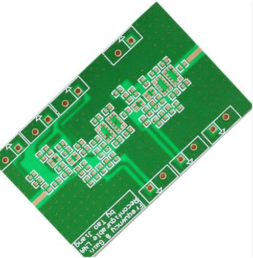
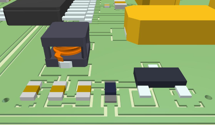
When designing printed circuit boards (PCBs) for radio frequency (RF) applications, one critical component that demands careful consideration is the RF edge connector. These connectors serve as the interface between the PCB and external RF components, ensuring signal integrity and minimizing losses. The design considerations for PCB RF edge connectors are multifaceted, encompassing electrical, mechanical, and thermal aspects to achieve optimal performance.
To begin with, the electrical performance of an RF edge connector is paramount.
The connector must maintain signal integrity by minimizing insertion loss, return loss, and crosstalk. Insertion loss refers to the reduction in signal strength as it passes through the connector, while return loss measures the amount of signal reflected back towards the source. Both parameters are crucial in high-frequency applications, where even minor losses can significantly impact performance. To mitigate these issues, designers often employ impedance matching techniques, ensuring that the impedance of the connector closely matches that of the transmission line. This alignment reduces reflections and enhances signal transmission.
Moreover, the choice of materials plays a significant role in the electrical performance of RF edge connectors.
Conductive materials such as gold or silver are commonly used for the contact surfaces due to their excellent conductivity and resistance to oxidation. Additionally, the dielectric materials used in the connector must exhibit low dielectric constant and low loss tangent to minimize signal degradation. These materials help maintain the integrity of the high-frequency signals as they traverse the connector.
Transitioning to mechanical considerations, the physical design of the RF edge connector must ensure robust and reliable connections.
The connector should provide a secure fit to prevent disconnections due to vibrations or mechanical stress. This is particularly important in applications such as aerospace or automotive, where environmental conditions can be harsh. The mechanical design also includes considerations for ease of assembly and disassembly, allowing for efficient maintenance and replacement when necessary.
Furthermore, the size and form factor of the RF edge connector must align with the overall design of the PCB.
As electronic devices continue to shrink in size, the connectors must also be compact without compromising performance. Designers often face the challenge of balancing the need for miniaturization with the requirement for maintaining electrical and mechanical integrity. Advanced manufacturing techniques and materials have enabled the development of smaller yet highly efficient connectors, addressing this challenge effectively.
Thermal management is another critical aspect in the design of PCB RF edge connectors.
High-frequency signals can generate significant heat, which, if not properly managed, can lead to performance degradation or even failure of the connector. Effective thermal management strategies include the use of heat sinks, thermal vias, and conductive materials that facilitate heat dissipation. Ensuring that the connector can operate within the specified temperature range is essential for maintaining long-term reliability and performance.
In conclusion, the design considerations for PCB RF edge connectors are comprehensive, requiring a balanced approach to electrical, mechanical, and thermal aspects. By carefully selecting materials, employing impedance matching techniques, and ensuring robust mechanical design, engineers can develop connectors that meet the stringent demands of high-frequency applications. As technology continues to advance, ongoing innovation in connector design will be essential to support the ever-increasing performance requirements of modern electronic devices.
Top Materials for High-Frequency PCB RF Edge Connectors
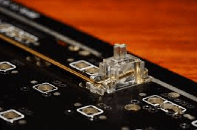
When designing high-frequency printed circuit boards (PCBs), the choice of materials for RF edge connectors is paramount. These connectors are critical in ensuring signal integrity and minimizing losses, especially in applications where performance and reliability are non-negotiable. The materials used in RF edge connectors must exhibit excellent electrical properties, mechanical strength, and thermal stability to meet the stringent demands of high-frequency operations.
One of the top materials for high-frequency PCB RF edge connectors is beryllium copper (BeCu).
Beryllium copper is renowned for its exceptional electrical conductivity and mechanical resilience. It combines the strength of beryllium with the conductivity of copper, making it an ideal choice for connectors that must endure repeated mating cycles without significant wear. Additionally, BeCu’s excellent thermal conductivity helps dissipate heat generated during high-frequency operations, thereby maintaining the integrity of the signal.
Another material frequently used in high-frequency RF edge connectors is phosphor bronze.
Phosphor bronze is an alloy of copper with tin and phosphorus, which enhances its strength and corrosion resistance. This material is particularly valued for its ability to maintain consistent electrical performance over time, even in harsh environmental conditions. The tin content in phosphor bronze improves its solderability, ensuring secure and reliable connections. Moreover, its mechanical properties make it suitable for applications requiring high durability and resistance to fatigue.
Gold plating is often applied to the contact surfaces of RF edge connectors to further enhance their performance.
Gold is an excellent conductor of electricity and is highly resistant to oxidation and corrosion. This ensures that the connectors maintain low contact resistance and high reliability over extended periods. The use of gold plating is especially critical in high-frequency applications where even minor signal degradation can lead to significant performance issues. Although gold is more expensive than other materials, its benefits in terms of reliability and performance often justify the cost.
In addition to metallic materials, certain high-performance plastics are also used in the construction of RF edge connectors.
Polytetrafluoroethylene (PTFE), commonly known as Teflon, is one such material. PTFE is prized for its low dielectric constant and low loss tangent, which are essential for maintaining signal integrity at high frequencies. Its excellent thermal stability and chemical resistance make it suitable for use in a wide range of environments. PTFE’s flexibility also allows for the design of connectors that can accommodate various PCB layouts and configurations.
Liquid crystal polymer (LCP) is another advanced plastic material used in high-frequency RF edge connectors.
LCP offers a unique combination of high strength, low dielectric constant, and low moisture absorption. These properties make it an excellent choice for connectors that must operate in high-frequency and high-temperature environments. LCP’s dimensional stability ensures that the connectors maintain their shape and performance over time, even under mechanical stress.
In conclusion, the selection of materials for high-frequency PCB RF edge connectors is a critical aspect of ensuring optimal performance and reliability. Beryllium copper, phosphor bronze, gold plating, PTFE, and liquid crystal polymer are among the top materials used in these applications. Each material offers unique advantages that cater to the specific requirements of high-frequency operations. By carefully choosing the appropriate materials, designers can achieve the desired balance of electrical performance, mechanical strength, and thermal stability, thereby ensuring the success of their high-frequency PCB designs.
Common Applications of PCB RF Edge Connectors in Modern Electronics
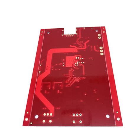
PCB RF edge connectors are integral components in modern electronics, serving as critical interfaces for high-frequency signal transmission. These connectors are designed to provide a reliable and efficient means of connecting printed circuit boards (PCBs) to various RF (radio frequency) devices, ensuring minimal signal loss and maintaining signal integrity. Their applications span a wide range of industries, each leveraging the unique advantages offered by these connectors.
One of the most prominent applications of PCB RF edge connectors is in telecommunications.
With the ever-increasing demand for faster and more reliable communication networks, these connectors play a vital role in the infrastructure of cellular base stations, satellite communication systems, and broadband networks. They facilitate the seamless transmission of high-frequency signals between different components, ensuring that data is transmitted with minimal interference and maximum efficiency. This is particularly crucial in 5G technology, where the need for high-speed data transfer and low latency is paramount.
In addition to telecommunications, PCB RF edge connectors are extensively used in the aerospace and defense sectors.
These industries require robust and reliable components that can withstand harsh environmental conditions and maintain performance under extreme stress. RF edge connectors are employed in radar systems, avionics, and military communication devices, where they ensure the accurate transmission of critical data. The connectors’ ability to maintain signal integrity in high-frequency applications makes them indispensable in these high-stakes environments.
The medical field also benefits significantly from the use of PCB RF edge connectors.
Medical imaging equipment, such as MRI and CT scanners, rely on these connectors to transmit high-frequency signals with precision. The connectors’ ability to handle high data rates and maintain signal clarity is essential for producing accurate diagnostic images. Furthermore, RF edge connectors are used in various medical monitoring devices, where reliable signal transmission is crucial for patient safety and effective treatment.
Consumer electronics represent another major application area for PCB RF edge connectors.
Devices such as smartphones, tablets, and laptops require efficient and compact connectors to manage the high-frequency signals associated with wireless communication and data transfer. The miniaturization of electronic components has driven the development of smaller and more efficient RF edge connectors, which are now a staple in the design of modern consumer gadgets. These connectors ensure that devices can communicate wirelessly with minimal signal loss, enhancing the overall user experience.
Moreover, the automotive industry has seen a growing adoption of PCB RF edge connectors, particularly with the advent of advanced driver-assistance systems (ADAS) and autonomous vehicles.
These systems rely on high-frequency signals for functions such as radar, lidar, and vehicle-to-everything (V2X) communication. RF edge connectors provide the necessary reliability and performance to ensure that these systems operate effectively, contributing to the safety and efficiency of modern vehicles.
In conclusion, PCB RF edge connectors are indispensable in a variety of modern electronic applications. Their ability to transmit high-frequency signals with minimal loss and maintain signal integrity makes them a critical component in telecommunications, aerospace and defense, medical equipment, consumer electronics, and automotive systems. As technology continues to advance, the demand for reliable and efficient RF edge connectors is expected to grow, further solidifying their role in the development of cutting-edge electronic devices and systems.
Troubleshooting Signal Integrity Issues in PCB RF Edge Connectors
When dealing with PCB RF edge connectors, ensuring signal integrity is paramount for the optimal performance of high-frequency circuits. Signal integrity issues can manifest in various forms, such as signal loss, reflection, and crosstalk, which can significantly degrade the performance of RF systems. Therefore, troubleshooting these issues requires a systematic approach to identify and mitigate the underlying causes.
To begin with, one of the primary factors affecting signal integrity in PCB RF edge connectors is impedance mismatch.
Impedance mismatch occurs when the impedance of the connector does not match the impedance of the transmission line, leading to signal reflections. These reflections can cause signal degradation and loss of data integrity. To address this, it is essential to ensure that the impedance of the RF edge connector is matched to the characteristic impedance of the transmission line. This can be achieved through careful design and selection of connectors that are specifically rated for the desired impedance.
In addition to impedance mismatch, another common issue is signal loss due to poor connector quality or improper installation.
High-frequency signals are particularly susceptible to losses caused by substandard connectors or improper soldering techniques. To mitigate this, it is crucial to use high-quality connectors that are designed for RF applications and to follow proper installation procedures. This includes ensuring that the connectors are securely attached to the PCB and that there is minimal resistance at the connection points.
Moreover, crosstalk is another significant concern in RF edge connectors, especially in densely packed PCBs.
Crosstalk occurs when a signal from one transmission line interferes with an adjacent line, leading to signal degradation. To minimize crosstalk, it is important to maintain adequate spacing between transmission lines and to use shielding techniques. For instance, placing ground planes between signal layers can help to isolate signals and reduce crosstalk. Additionally, using differential signaling can also help to mitigate crosstalk by ensuring that any interference affects both lines equally, thereby canceling out the noise.
Furthermore, environmental factors such as temperature and humidity can also impact the performance of RF edge connectors.
High temperatures can cause thermal expansion, leading to mechanical stress and potential damage to the connectors. Similarly, high humidity can lead to corrosion and degradation of the connector materials. To address these issues, it is important to use connectors that are rated for the operating environment and to implement proper thermal management and environmental protection measures.
Another critical aspect of troubleshooting signal integrity issues is the use of appropriate testing and measurement techniques.
Tools such as vector network analyzers (VNAs) and time-domain reflectometers (TDRs) can be invaluable in diagnosing signal integrity problems. These tools can help to identify impedance mismatches, signal loss, and crosstalk by providing detailed measurements of the signal characteristics. By analyzing these measurements, engineers can pinpoint the root causes of signal integrity issues and implement corrective actions.
In conclusion, troubleshooting signal integrity issues in PCB RF edge connectors requires a comprehensive approach that addresses impedance matching, connector quality, crosstalk, environmental factors, and proper testing techniques. By carefully considering these factors and implementing best practices, engineers can ensure that their RF systems perform optimally and maintain high signal integrity. This, in turn, leads to more reliable and efficient communication systems, which are essential in today’s increasingly connected world.

